8
Lester's Site
Kristin A. Kuckelman
Contents
- Surface Architecture (Sampling Stratum 1)
- Sampling Unit 97N/125E
Sampling Unit 100N/102E
Surface Architecture (Sampling Stratum 1) Summary
- Pit Structures (Sampling Stratum 2)
- Structure 3 (Kiva)
- Surface 1
- Features
- Feature 1 (Bench 6)
Feature 2 (Ventilator Tunnel)
Feature 3 (Bench 1)
Feature 4 (Pilaster 1)
Feature 5 (Hearth)
Feature 6 (Deflector) - Artifacts
- Stratigraphy
Dating
Interpretations - Pit Structures (Sampling Stratum 2) Summary
- Courtyard (Sampling Stratum 3)
- Sampling Units 95N/113E and 96N/113E
Sampling Unit 102N/120E
- Courtyard (Sampling Stratum 3) Summary
- Inner Periphery (Sampling Stratum 4)
- Sampling Unit 94N/100E
Sampling Unit 92N/101E- Sampling Unit 82N/105E
Sampling Unit 78N/120E
Sampling Unit 86N/131E
Inner Periphery (Sampling Stratum 4) Summary - Sampling Unit 82N/105E
- Midden (Sampling Stratum 5, Nonstructure 1)
- Sampling Unit 91N/126E
- Stratigraphy
Feature 2 (Burial)
Feature 3 (Retaining Wall)
Feature 4 (Structure Wall) - Midden (Sampling Stratum 5, Nonstructure 1) Summary
- Outer Periphery (Sampling Stratum 6)
- Sampling Units 76N/106E, 67N/113E, and 72N/118E
Sampling Unit 68N/124E
Sampling Unit 70N/126E
Outer Periphery (Sampling Stratum 6) Summary
- Outer Periphery (Sampling Strata 7 and 8)
- Stratigraphy
Feature 1 (Rock Alignment)
Outer Periphery (Sampling Strata 7 and 8) Summary
Introduction
Lester's Site, 5MT10246, was first recorded as site CC87-284 in 1987 by a Crow Canyon Survey crew (Adler 1988). The site was selected for testing as part of the Sand Canyon Archaeological Project Site Testing Program in 1989. Excavation was initiated in June 1989, but most of the fieldwork at Lester's Site occurred during the 1990 field season. Mark D. Varien directed excavations, and Kristin A. Kuckelman assisted.
The site was selected for testing because it seemed likely that excavation would produce data useful in answering the research questions posed by the Site Testing Program. Of particular interest was the community of sites surrounding Sand Canyon Pueblo. Determining which sites were occupied at the same time as Sand Canyon was one of the goals of the Testing Program, and the high proportion of Mesa Verde Black-on-white pottery observed on the modern ground surface at Lester's Site indicated possible contemporaneity. In addition, permanent habitations such as Lester's Site are more likely than other types of sites to yield tree-ring samples for absolute dating. Tree-ring dates are critical for fine-tuning chronology and establishing contemporaneity between sites. Finally, the cliff-base/talus-slope location of Lester's Site expanded the range of topographic settings sampled by the Testing Program and allowed us to evaluate whether setting was related to site function or to time of occupation. For additional discussion of the Site Testing Program research objectives, see Chapter 1 of this volume.
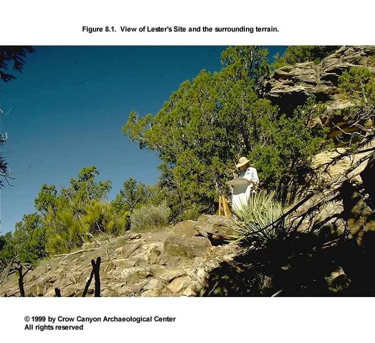
Lester's Site is located in Montezuma County, southwestern Colorado. The site is below the north rim of Sand Canyon, 550 m west of the canyon head (Figure 1.7). The architecture at the site is located on a narrow bench immediately beneath the canyon rim; the midden is on the talus slope below the bench (Figure 8.1). The elevation of the site ranges from 2066 m (6780 ft) on the bench to 2042 m (6700 ft) in the area of the downslope artifact scatter. The slope of the site varies between 7 degrees and 34 degrees. The closest permanent water source during the occupation of the site was the spring at Sand Canyon Pueblo, which was 170 m north-northeast of Lester's Site.
The primary vegetation on the site is pinyon-juniper. Also present are Mormon tea (Ephedra viridis), sagebrush (Artemisia tridentata), prickly pear (Opuntia sp.), yucca, and grasses. Scrub oak (Gambel oak) (Quercus gambelii) grows at the south edge of the site, along Sand Creek.
The location of the site within the canyon and the steep, rocky terrain have discouraged use of the site area during the historic period. No evidence of vandalism was observed; however, the proximity of highly visible Sand Canyon Pueblo has probably resulted in the unofficial collection of artifacts from the surface of Lester's Site.
The steep, rugged topography at the site masks surface remains that might be more observable and interpretable on mesa-top sites. The surface remains observable at the site consist of two walled alcoves, three surface structures, several general areas of rubble, several sections of retaining walls, one observable pit structure depression, and a stained midden (Figure 8.2). The presence and location of a second pit structure was accurately noted prior to excavation, although no depression was detectable. A slight widening of the terrace in that location, and a section of curved masonry wall, suggests the presence of the structure.
Portions of the walls of the three nonalcove surface structures were visible on the modern ground surface. One of these rooms appears to be a small, nearly square structure that abuts the cliff face near the west edge of the site. Another surface structure occupies a small terrace just below the main site retaining wall near the east edge of the site. This structure may be rectangular, oval, or D-shaped. The final observable surface structure wall is associated with a boulder overhang downslope from the structure just mentioned.
The surface remains were used to define the sampling strata for the stratified random sample (Figure 8.3). Areas of rubble that apparently resulted from the collapse of surface structures (rather than retaining walls) were designated Sampling Stratum 1. Three such areas were defined. Sampling Stratum 2 denotes the two pit structure areas. The courtyard, or Sampling Stratum 3, surrounds the architectural space; its outer boundary roughly coincides with the main site retaining wall. Sampling Stratum 4 is the "inner periphery," a strip of area that surrounds the cultural units at the site. Sampling Stratum 5 is the midden, indicated by stained soil and a greater density of artifacts than is present elsewhere on the site. Sampling Strata 6, 7, and 8 are designated as the "outer periphery." Sampling Strata 6 and 7 were designed to help define and quantify the amount of downslope artifact movement that resulted from secondary refuse being deposited on such a steep slope. Sampling Stratum 8 includes the east and west reaches of the artifact scatter.
Testing at Lester's Site consisted of the excavation of 45 randomly selected 1-×-1-m test pits and several judgment units (Figure 8.3). The judgment units consisted of four 1-×-1-m pits, one 1-×-2-m trench, one 1-×-0.5-m trench, and one small, irregular pit adjacent to unit 91N/126E. The irregular pit was excavated to expose a small portion of a burial that extended outside the random unit. The major cultural units exposed during the course of these excavations are shown in Figure 8.4.
The site grid is oriented to the cliff face and to the slope of the site. Grid north is 36 degrees west of magnetic north, or 22.5 degrees west of true north. Rebar set in concrete marks the points 100N/100E and 100N/132E; these rebars were also used as secondary vertical datums. The primary vertical datum is a nail in a cliff-face crevice at approximately 104N/113E. The top of the nail was assigned an elevation of 88.47 m to coincide with the arbitrary elevation system already in use in the Sand Canyon Pueblo excavations.
Although no attempt was made to impose the grid system at Sand Canyon Pueblo on Lester's Site, the relationship between these two grids was recorded. The grid at Sand Canyon Pueblo is oriented true north; the 100N/100E rebar at Lester's Site is grid point 826.00N/951.24E in the Sand Canyon system.
The proximity of Lester's Site to Sand Canyon Pueblo indicates that Lester's Site may be associated with, or even part of, the larger site. Lester's Site was surveyed and assigned a separate site number in 1987 because this area had not been included during the surveying and mapping of Sand Canyon Pueblo and because Lester's Site is outside the site-enclosing wall of Sand Canyon Pueblo. This will be discussed further in the Site Summary and Conclusions section of this report.
The following report is organized by sampling strata, which will be discussed in numerical order. The cultural units that were tested are described with the sampling stratum in which they were located.
Surface Architecture (Sampling Stratum 1)
Sampling Stratum 1 is the surface architecture sampling stratum. This stratum was designed to sample areas of rubble resulting from the collapse of surface structures. Two natural alcoves in the cliff face at the northern edge of the site were also included, as surface architecture was associated with them. Retaining walls were not included in this sampling stratum but were assigned to Sampling Stratum 3 (courtyard).
Sampling Stratum 1 contains a total of 168 sampling units. Four 1-×-1-m randomly selected units were excavated to sample this stratum (100N/102E, 95N/106E, 103N/118E, and 97N/125E). One of these random units (97N/125E) exposed sections of a retaining wall, upper lining wall, bench and pilaster of Structure 1 (kiva) and thus ideally would have been within the area designated Sampling Stratum 2 (pit structures).
In addition to the random excavations, a limited amount of judgmental excavation was necessary. One 1-×-1-m judgment unit (102N/118E) was excavated to more fully expose a masonry wall found in random unit 103N/118E and to determine if that wall served as the north wall of a surface structure to the south. One 1.0-×-0.5-m trench (its southwest corner is 104N/118E) was excavated north of the same masonry wall in order to learn more about the horizontal extent and the function of the structure (Structure 2) encountered in random unit 103N/118E. The excavation of these judgment units also served to extend the north-south stratigraphic exposure observable in the west face of random unit 103N/118E.
Structure 2 (Alcove Room)
Structure 2 is an alcove room in the base of the cliff face at the north edge of the site (Figure 8.5). An east-west segment of masonry wall was exposed in random unit 103N/118E. This was interpreted to be a portion of a longer wall that enclosed the alcove. A north-south judgmental test trench (1.0 × 0.5 m) was excavated north of, and adjacent to, the random unit in order to gather additional data about the function and horizontal extent of the structure and to more fully understand postoccupational filling processes. If the entire alcove is one room, its approximate measurements are 4.0 m east-west and 2.2 m north-south.
Construction
The construction methods of the architectural features observed in Structure 2 are described in this section, including the walls, roof, and surface.
Walls. Excavations in Structure 2 exposed a 1-m-long section of an east-west masonry wall. Because this wall is at the south edge of a natural alcove, it is interpreted to be the south wall of a structure. The north, east, and west walls are formed by the natural walls of the alcove.
Some of the exposed masonry wall is semicoursed and of compound construction with rubble core. However, a large portion of the exposed section of wall is formed by a boulder that spans the full width of the wall. This boulder appears to have been intentionally positioned during the construction of the wall; the exposed portion of the boulder is atop three to five vertical courses of masonry (Figure 8.6).
The north and the south faces of the wall are of different heights, and the bottoms of these faces rest at different levels. This is because there is a significant local drop in the elevation of the undisturbed decomposing sandstone bedrock on which the wall was constructed. Thus, the south face of the wall rests at an elevation of 84.75 m and is 113 cm high, and the north face rests at 85.14 m and is 100 cm high. The width of the wall varies from 62 cm at the west end of the exposed section to 50 cm at the east end.
All of the rocks in the exposed section of this wall are sandstone. Most rocks used in the construction of the north face are tabular; nearly half of the south face is of block construction. Most rocks in the north face are unshaped, and the remainder are pecked or flaked. More than half of the south face is composed of stones with pecked surfaces, and the remainder are unshaped. The primary reason for the abundance of unshaped tabular sandstone in the north face of this wall is that between two and five courses of the masonry form the foundation of the wall, which is below the prepared floor surface within Structure 2 and thus was hidden from view. The foundation beneath the south face is decomposing sandstone bedrock.
A small amount of tabular and chunk chinking occur in the north face of the wall only; most of this is also below floor level. The mortar in both faces averages 3 cm thick; below floor level it is as much as 11 cm thick. The mortar is a strong brown fine sandy loam containing tiny sandstone bits and calcium carbonate flecks. No plaster was observed on either face of this wall.
Roof. The method by which Structure 2 was roofed is unknown. No post holes were observed in the exposed portion of Surface 1, and no beam sockets could be detected in the alcove walls. The natural overhang of the alcove would have been inadequate as a roof, because the dripline is inside the south wall of the structure. Also, the top of the alcove is so high above the prepared floor that even if the dripline were outside the wall, the interior of the room would still have been largely exposed to the elements. The only evidence of roofing was contained in the fill of the structure (see the description of stratigraphy). A large shaped slab resting just above Surface 1 may have been associated with the roof.
Surface 1. One surface was defined in Structure 2. This is a prepared floor formed of red brown adobe and containing small bits of sandstone and flecks of charcoal. The top of this 0.5- to 1-cm-thick adobe layer has a grayish cast, which may be an ash residue. The surface is nearly level and has been compacted through use. A masonry wall bounds this surface on the south. The natural alcove walls presumably bound the surface on the north, east, and west.
The construction of the floor surface began with leveling, apparently after the masonry south wall was constructed. In the excavated portion of the room, between 18 and 30 cm of intentional fill was placed atop rocks and natural decomposing sandstone bedrock. The adobe surface was then applied.
Surface 1
Several artifacts were within 5 cm of the floor. No features were identified in the excavated portion of this room.
Artifacts. Several sandstone rocks rested on the adobe floor. These are interpreted to be postoccupational structural collapse, with one exception. One end of a large (61 × 28 × 9 cm) shaped sandstone slab rested on, or actually had been impressed 2 to 3 cm into, the floor surface (Figure 8.5). The other end of the slab rested against the north face of the boulder that formed part of the south wall of the structure. The shaping and positioning of this slab suggest that it served as a door slab.
One additional artifact--a Pueblo III White Painted bowl rim sherd (PL 1)--was found directly on the floor near the north end of the exploratory trench. Several other artifacts were recovered within 5 cm of the floor surface and may be associated with the use of the room: three Pueblo III White Painted sherds with carbon paint, six corrugated body sherds, and five Late White Unpainted sherds. From the construction material beneath Surface 1 (Stratum 5, Figure 8.6), one Mesa Verde Black-on-white sherd was recovered.
Stratigraphy
Figure 8.6 depicts the north-south stratigraphic profile along the 118E grid line both within Structure 2 and immediately to the south of this structure. The fill of Structure 2 is predominantly naturally deposited structural collapse. Seven strata were defined; these are described from the modern ground surface down to undisturbed sterile material.
Stratum 1 is a dark brown sandy loam with a moderate number of calcium carbonate and charcoal flecks; very small gravels; small, sparse pockets of unburned adobe; and abundant sandstone rubble. South of the masonry wall the stratum is slightly more homogeneous and has no charcoal flecks or adobe nodules. There is some charcoal staining toward the north end of the profile.
This latest postabandonment stratum was primarily naturally deposited, but there is some evidence (charcoal fragments and staining) in this stratum of recent use of the alcove. A historic campfire can be postulated as the source of this charcoal.
Stratum 2 is a homogeneous, brown sandy loam containing an abundance of sandstone rubble, some small rocks and gravels, calcium carbonate flecks, and fewer charcoal flecks than are present in Stratum 1. Several of the larger rocks have one or more pecked surfaces, and a few have been burned. Some animal disturbance is observable in this stratum.
Stratum 2 has the most homogeneous sediment of any stratum in the profile and contains a great deal of wall fall rubble. Stratum 2 also contains a higher percentage of clay than Stratum 1, probably resulting from adobe "melt" from the structure wall(s), the roof, or both. This stratum was deposited as the last episode of structural collapse. The source of the thermally altered rocks is unknown.
Stratum 3 is a very mottled, strong brown sandy loam, with many inclusions. The dominant inclusion is sandstone rubble, but also present are very fine gravels, pockets of unburned adobe and calcium carbonate nodules as large as 5 cm in diameter, sparse charcoal flecks, and small, irregular pockets of ashy gray clay. This is a rapidly deposited stratum of collapsed construction material consisting of wall fall or wall fall and roof fall combined. The origin of the clay pockets is unknown.
Stratum 4 is a loosely consolidated, yellowish brown silty sand containing so many inclusions that it was difficult to analyze the sediment texture. Sandstone rubble is shown on the map; also observed were many smaller sandstone rocks (down to gravel-size), sparse adobe nodules as large as 3 cm in diameter, and abundant calcium carbonate flecks. This stratum is massive, with many inclusions too large to have been wind deposited and few or no water-laid sediments. It was the initial deposit after the structure was abandoned, as it contacts Surface 1 in most of the excavated area. This stratum contains either roof fall, wall fall, or both.
Not observed in this profile face, but noted during excavation in the eastern half of 103N/118E, was a layer of slightly browner adobe nodules. At that location, this layer was below Stratum 4 and in direct contact with Surface 1. Thus, that layer is almost certainly related to roof construction. It was deposited shortly after the structure was abandoned, as no natural deposits had accumulated on the floor prior to that. No vegetal roofing material was observed anywhere in this profile, nor was any observed during the excavations in this structure.
Stratum 5 is a very mottled, yellowish brown fine sandy loam. This deposit contains adobe nodules up to 5 cm in diameter, decomposing sandstone pieces up to 3 cm in diameter, burned adobe flecks, very tiny gravels, and many fewer calcium carbonate flecks than in Stratum 4. This stratum is intentional construction fill between the Surface 1 adobe floor and decomposing sandstone bedrock. It was used as a leveling agent prior to floor construction and subsequent to the construction of the masonry wall. This is the only culturally deposited material in this stratigraphic profile.
Strata 6 and 7 are deposits south of Structure 2, but they are related to the collapse of that structure. Stratum 6 is a homogeneous, brown, very fine sandy loam. It contains massive rubble, a few small sandstone bits, and very sparse adobe and calcium carbonate flecks. Pecking is common on the larger rocks. Stratum 6 is postabandonment wall collapse from the south wall of Structure 2.
Stratum 7 is a yellowish brown fine sandy loam containing a series of wash lenses, decomposing sandstone rocks as large as 5 cm in diameter, sparse charcoal flecks, lenses of calcium carbonate flecks, lenses of small sandstone bits and coarse sand, and small, thin gray ash lenses near the bottom of the structure wall. There is also decomposing adobe in the form of "melt," nodules, and wash lenses. This stratum appears to be material that accumulated and washed downslope away from the south wall of Structure 2. The adobe lens at the bottom of the wall is inferred to be associated with wall construction or to be "melt" off the wall rather than being a prepared floor, because it is neither uniform nor continuous.
There is no material in Stratum 6 or 7 similar to Strata 3 and 4 inside Structure 2. This absence and the apparent absence of a prepared surface suggest that there is no surface structure adjacent to Structure 2 on the south.
Dating
No absolute dating samples were collected from Structure 2. The pottery recovered in the fill and on the floor of the room suggests that this structure is contemporaneous with the other architecture documented at Lester's Site. Tree-ring and archaeomagnetic dates for Structure 1 (kiva) indicate that construction occurred on this late Pueblo III site in A.D. 1270 or shortly thereafter.
Interpretations
Structure 2 is a room formed primarily by a natural alcove in the base of the cliff face at the north edge of the site. The enclosing of the alcove was effected by the construction of a compound masonry wall across the alcove opening. The function of the structure is unknown; there were few artifacts in the fill and only one sherd on the floor surface. No features were observed in the small area of floor exposed during excavations.
There is some evidence, however, to suggest that the room was used for habitation rather than for storage. The grayish cast to the adobe floor may be a thin ash deposit. If so, it would suggest the presence of a fire pit in the structure. Substantial secondary refuse ash deposits were recorded in a random unit (102N/120E, Sampling Stratum 3) a few meters downslope southeast of the structure. These deposits suggest the presence of a fire pit nearby.
Sampling Unit 95N/106E
Excavations in this unit exposed a section of retaining wall, designated Feature 1 of Sampling Stratum 1. The location of the wall indicates that it is associated with the construction of Structure 3 (kiva) just upslope to the north, rather than being a part of the main, courtyard-enclosing retaining wall (Figure 8.4).
Feature 1 (Retaining Wall)
A 1-m-long section of curved, east-west retaining wall was exposed along the north edge of the unit (Figure 8.4), just south of Structure 3 (kiva). This section is 90 cm high, and 30 cm of width was exposed during excavation (Figure 8.7). The wall is constructed of large, horizontally coursed sandstone blocks that show little evidence of shaping. The cross section was not observable. Mortar joints range from 8 cm thick to nonexistent. The mortar is a brown sandy loam containing charcoal flecks.
This retaining wall apparently was constructed to stabilize the natural slope and to create a relatively level courtyard for Structure 3 (kiva). The wall may have been constructed prior to, or concurrently with, Structure 3.
Stratigraphy
Four strata were defined in the portion of this unit not occupied by the retaining wall (Figure 8.7). The stratigraphy includes natural deposits, secondary refuse, structural collapse, and possibly construction fill. The stratigraphy is discussed from the modern ground surface down to undisturbed sterile deposits. Modern ground surface slopes 35 degrees down to the south in this unit.
Stratum 1 is a very loosely compacted, brown to dark brown coarse sandy loam. Included within this sediment are charcoal flecks, some sandstone wall fall, small bits of sandstone and unburned adobe, and a moderate number of artifacts. This material appears to be a combination of secondary refuse and aeolian, alluvial, and colluvial sediment. At least some of the stratum accumulated during the occupation of the site, but some may be postoccupational. It is also possible that the uppermost deposits have eroded downslope.
Stratum 2 is similar to Stratum 1 but is much more compact and contains no construction-size sandstone rocks. Artifact density is lower as well. This stratum thus contains no wall collapse, and less secondary refuse than Stratum 1; it accumulated during the occupation of the site.
Stratum 3 is a very pale brown, medium to coarse sand with sparse charcoal flecks. Small, angular sandstone rocks occupy approximately 50 percent of the stratum's volume. The base of Feature 1 (retaining wall) is level with the top of Stratum 3; this stratum may be constructional fill designed to provide a level surface as a foundation for the retaining wall.
Stratum 4 is a dark brown to strong brown sandy clay that becomes finer textured with increasing depth. No inclusions were observed, and this stratum is believed to be undisturbed sterile sediment.
Sampling Unit 97N/125E
This random unit is within the surface architecture sampling stratum, but excavation exposed a portion of the east edge of Structure 1 (kiva). A retaining wall, upper lining wall, pilaster, and section of bench were encountered in this unit. Therefore, this unit will be discussed under the Structure 1 heading below.
Sampling Unit 100N/102E
Although located in an area of rubble, this unit did not contain any surface architecture, and sterile sediment was exposed at a relatively shallow depth. Modern ground surface slopes 17 degrees down to the southwest. Stratum 1 consists of wall fall in naturally deposited red brown sandy sediments. At a depth of 6 to 12 cm below modern ground surface, Stratum 2 was encountered. This is a stratum of gray brown sandy silt with inclusions of charcoal nodules and hundreds of sandstone rocks, the largest of which is 44 × 25 × 22 cm. The sandstone is discolored the same hue as the sediments but does not appear to be thermally altered. A number of large mammal bones were recovered in this stratum. Undisturbed sterile deposits were encountered 16 cm below the modern ground surface on the south edge of the unit and 40 cm below the modern ground surface on the north edge of the unit.
Surface Architecture (Sampling Stratum 1) Summary
The sampling of the surface architecture stratum resulted in the definition of one alcove room and a retaining wall constructed around a kiva (Structure 3). Four random 1-×-1-m units were excavated in this stratum; one of these exposed the east edge of Structure 1 (kiva). Random unit 103N/118E overlapped the south wall of Structure 2 (alcove room). The excavation of adjacent judgment units clarified the construction of this room and provided evidence that no room is present south of Structure 2. No features were defined within this room, but there is evidence to suggest that it contains a hearth and therefore was used for habitation. Dating of Structure 2 to the late Pueblo III period is based on the presence of Mesa Verde Black-on-white pottery in the construction fill beneath the floor.
A short section of a retaining wall was exposed in random unit 95N/106E. This wall appears to have been constructed prior to, or during, the construction of Structure 3 (kiva) to stabilize the talus slope and to provide a more level surface for the kiva. This retaining wall is clearly separate from the main site retaining wall that encloses the entire architecture terrace at the site (Figure 8.4).
None of the 1-×-1-m units within a second alcove room or three additional surface structures were chosen for excavation during the random selection process. Thus, these structures were not tested. The untested alcove room (Figure 8.4) is smaller than the tested alcove room (Structure 2), both horizontally and vertically, and the bedrock floor is exposed. A wall across the opening apparently enclosed the room, which is probably too small to have been used for anything except storage.
One untested surface room abuts the cliff face near the west edge of the site (Figure 8.4). The room is a very small, nearly square room of unknown function. Another probable surface structure occupies a small terrace just below the retaining wall near the east edge of the site. Excavation of random unit 91N/126E (Sampling Stratum 5) exposed a segment of the west wall of this probable structure, which may be a rectangular, oval, or D-shaped surface room or tower.
A wall stub beneath a boulder overhang just south of the previously mentioned room indicates the presence of the third untested surface room. The location of this structure on the talus slope and beneath a boulder suggests that it was used as a storage room rather than as a dwelling. No direct evidence of additional surface rooms was observed, although one or more buried rooms may exist in the rubble areas surrounding the kivas (Figure 8.2).
Pit Structures (Sampling Stratum 2)
Sampling Stratum 2 is the pit structure sampling stratum. This sampling stratum contains 46 1-×-1-m units; four units were randomly selected for excavation (97N/107E, 98N/105E, 97N/122E, and 97N/124E). In addition, three judgment units were excavated in this stratum (1-×-1, 98N/106E; 1-×-2, 98N/107E; and 1-×-1, 97N/123E). Two of the judgment units were excavated in Structure 3 (kiva); one was excavated for logistical reasons, the second was excavated to expose and sample the hearth. The third judgment unit was excavated between the two random units in Structure 1 (kiva) as a safety precaution. One random unit in the surface architecture sampling stratum (97N/125E) overlapped the east wall of Structure 1 (kiva) and therefore will be discussed with the pit structure sampling stratum.
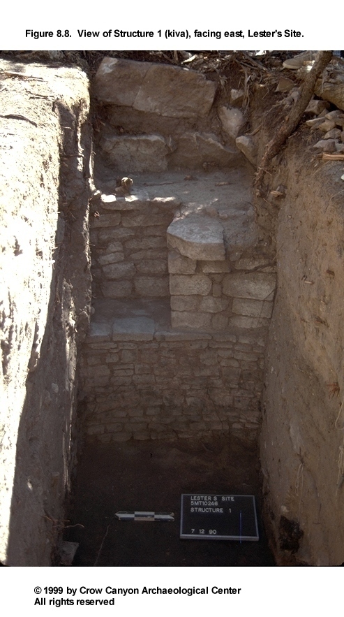
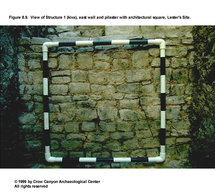
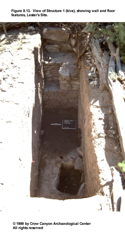
Structure 1 (Kiva)
Structure 1 is a burned, masonry-lined kiva (Figure 8.8, Figure 8.9, and Figure 8.10). The structure was sampled by excavating three randomly selected units (97N/122E, 97N/124E, and 97N/125E) and one judgmentally selected unit (97N/123E). These four units formed a 1-×-4-m trench. Sections of retaining wall, upper lining wall, and Bench 4, as well as most of Pilaster 5 and the hearth, were exposed in these units. The extrapolated diameter of the kiva is 4.0 m, bench face to bench face.
Construction
The architectural features observed in Structure 1 are described in this section, including the walls, roof, and surfaces.
Walls. Excavations in Structure 1 exposed sections of the retaining wall, upper lining wall, and bench face. The retaining wall was located outside the upper lining wall. Only the face of the retaining wall was exposed, so the width and the cross section cannot be described. The portion of wall exposed is constructed of large, irregular, unshaped sandstone blocks. The wall ranges between 48 and 66 cm high, and the top leans inward 5 to 8 cm (Figure 8.11). The short section of wall observed appears to be semicoursed. The mortar beds range from 5 to 20 cm thick. The base of the wall is level with the top of the upper lining wall, so excavation stopped at that level. The foundation of the retaining wall is either undisturbed sterile sediment left in place when the kiva pit was excavated or is construction fill placed behind the upper lining wall after the kiva masonry was constructed.
The upper lining wall was much more finely constructed than the retaining wall and is fully coursed. The exposed section is 53 cm long and 65 cm high, and the top leans inward 10 cm. The wall is a single stone wide and measures 20 cm thick. Small blocks and tabular sandstone were used to construct this wall. Approximately 75 percent of the rock faces in the upper lining wall have been pecked; a few others were flaked. The mortar beds range between 0.5 and 2.0 cm thick. This wall rests on the bench surface.
The bench face is fully coursed and well constructed. The exposed section is 1.01 m long and 79 cm high, and the top leans inward 9 cm. The masonry as measured at the horizontal bench surface is one course (22 cm) wide. Small blocks and tabular sandstone rocks make up the bench face; nearly all are pecked. A few tabular chinking stones are observable in this wall. The mortar joints range from 0.5 to 2.0 cm thick. The mortar is a pale brown to brown fine sandy clay containing small sandstone nodules and charcoal and calcium carbonate flecks. The foundation beneath the bench face is leveled sandstone bedrock.
Roof. Evidence of roof construction was observed in the form of burned roof fall that rested on the floor (Surface 1) of the kiva and in the presence of Pilaster 5. Charred wood in roof fall ranges from beams 15 cm in diameter down to twigs and shreds of bark. All 192 tree-ring samples collected from roof fall and submitted for analysis proved to be juniper.
The two strata of roof fall are described fully in the section on stratigraphy, but a brief description is included here as well. Stratum 9 is an intensely burned deposit that rests directly on the floor (Surface 1). It is a dark brown sandy loam with numerous inclusions: burned adobe roof casts; unburned adobe "melt"; charcoal flecks; burned beams, twigs, and bark; a few large sandstone rocks (18 cm long); a few small sandstone rocks and gravels; few or no calcium carbonate flecks; ash; and charred sediment. A moderate number of artifacts were recovered from this stratum, but their origin is uncertain. Refer to the discussion of Surface 1 (floor) artifacts below.
Stratum 8 is a less intensely burned deposit of roof fall. It consists of a dark brown sandy loam with burned adobe nodules, unburned adobe, charcoal pieces as large as a few centimeters in diameter, a few large sandstone rocks, numerous smaller sandstone rocks and gravels, and calcium carbonate flecks. Artifacts are sparse and were probably on the roof when it collapsed.
The only other evidence of the roof of Structure 1 is the pilaster (Feature 2). This pilaster is probably Pilaster 5 (numbered clockwise beginning at the southern recess) in a six-pilaster roof-support system, assuming that the structure is oriented to the north and the hearth is slightly south of center.
The roof fall deposits and pilaster as described above suggest that a typical cribbed kiva roof supported by six pilasters covered this structure. The absence of naturally deposited sediments on the floor and in roof fall indicates that the roof burned at abandonment and collapsed rapidly.
Surface 1. Surface 1 is the use surface, or floor, of Structure 1. This surface was constructed by applying 1 to 5 cm of adobe to the top of a layer of construction fill. The surface diverges from level by a maximum of 4 cm in the area observed. It is use compacted and in some areas is lightly charred from the burning of the roof.
Surface 2. Surface 2 is the construction surface below Surface 1. In the area of floor observed, Surface 2 was the result of two different construction techniques. East and north of the hearth (Figure 8.10), the surface was prepared by leveling sandstone bedrock. Along the east wall of the kiva at least, 4 cm of bedrock was removed. One to 7 cm of construction fill was then placed on the bedrock, presumably for further smoothing and leveling. This construction fill consists of dark grayish brown loam with small sandstone bits, calcium carbonate flecks, and sparse charcoal flecks. Surface 1 adobe was applied to the top of this layer of construction fill.
West of the hearth, a 40- to 60-cm-wide natural crevice (Figure 8.12) in the bedrock necessitated more complex floor construction. Beneath the construction fill in this area is an additional layer of adobe as much as 3.5 cm thick. This adobe was applied on top of a 3-cm-thick layer of charcoal-flecked yellow sand. A pollen scrape was taken from this adobe (Figure 8.10). Below this layer of intentionally deposited sand is undisturbed sterile sand and decomposing sandstone bedrock. This same crevice complicated the construction of the hearth (Features 3 and 4).
Surface 1
A number of features and artifacts are associated with Surface 1.
Features. Four features are associated with Surface 1--a segment of bench, a pilaster, and the original and final hearths (Figure 8.13).
Feature 1 (Bench 4): Feature 1 is the portion of bench exposed during excavations in Structure 1. It is thought to be a section of Bench 4, which would be the fourth bench segment, separated by pilasters, as numbered clockwise beginning at the southern recess. The portion of bench surface observed is level and measures 43 cm long and 44 cm deep. The surface is formed by the tops of the bench-facing rocks along the front of the bench and by small, tabular sandstone rocks elsewhere. The tabular rocks appear to have been set into the bench surface with the same mortar used in the other masonry observed in this kiva. The bench was not dismantled to discover the construction method, so it is not known if the bench surface is atop undisturbed sterile, or if there is construction fill beneath. No artifacts were recovered from this surface. An unanalyzed pollen scrape (Figure 8.10) was taken from beneath a thermally altered rock that was resting on the bench.
Feature 2 (Pilaster 5): Feature 2 is the portion of pilaster exposed during excavations in this kiva. If the kiva is oriented to the north, and the hearth is slightly south of the structure's center, then this pilaster is Pilaster 5, numbering clockwise from the southern recess. This pilaster is fully coursed, is five courses high, and is two to three courses deep. The uppermost course was damaged and displaced by a large juniper tree that was growing on top of it. The pilaster corners were carefully shaped to right angles by pecking, and the faces of all rocks on the pilaster face were also pecked. The pilaster was constructed after the bench but apparently before the upper lining wall, which abuts it.
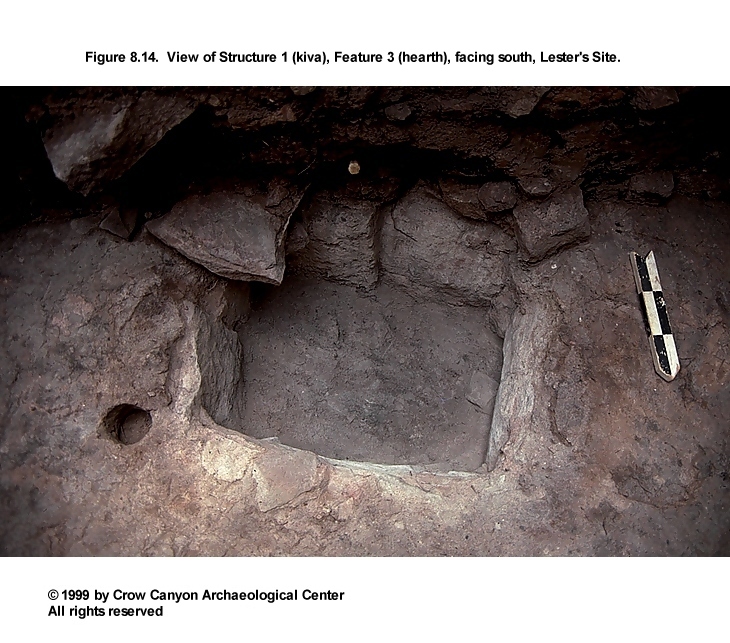
Feature 3 (Hearth): Feature 3 is the final hearth used in this kiva (Figure 8.12 and Figure 8.14). The feature underwent major remodeling during the occupation of the structure; the hearth as originally constructed is Feature 4. The southeast corner of Feature 3 extends outside the excavation unit; the following description is based on observations made of the exposed portion of the hearth.
Feature 3 is rectangular and is 77 cm long, 55 cm wide, and 33 cm deep. The walls are constructed of vertical sandstone slabs, bedrock, and adobe. The south wall, which is also the south wall of Feature 4 (hearth), is bedrock. The vertical slabs and adobe formed a pit inside Feature 4. The floor of Feature 3 was formed of slightly fire-reddened, ashy sand mixed with unburned, unconsolidated adobe, and it was above the floor of Feature 4.
The upper fill of this hearth was white ash; some grayer ash was present toward the bottom. Within the ash were sparse charcoal pieces and small nodules of burned adobe. Several of the charcoal pieces were large enough to be submitted for tree-ring dating. All Feature 3 ash was collected for flotation (five 1-liter samples) and fine-screen processing. No artifacts were recovered from fill.
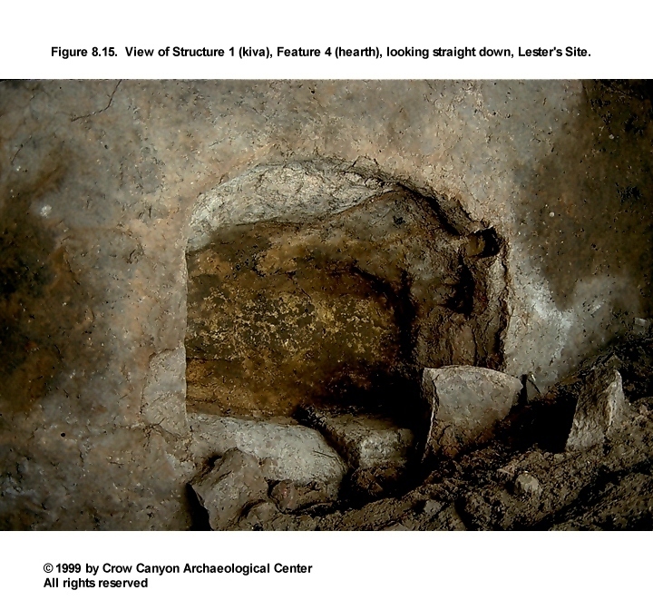
Feature 4 (Hearth): Feature 4 is the Structure 1 hearth as originally constructed; it is clearly associated with Surface 1 (the floor) of the kiva (Figure 8.12 and Figure 8.15). The southeast corner of the feature extends beyond the edge of the excavation unit; the description presented here is derived from observations of the exposed portion of the feature.
The pit for this hearth was created by enlarging a natural crevice in the sandstone bedrock (Figure 8.12). This crevice runs (grid) northwest-southeast, is 60 cm wide at the west end of the excavation unit, and ends just east of the hearth. The crevice is 5 to 10 cm wide at the bottom of Feature 4. After the crevice was enlarged, primarily by excavating the north face, five sandstone slabs were mortared into place with adobe to stabilize the west wall of the pit. These slabs prevented the naturally deposited sand fill within the crevice from collapsing into the hearth.
Feature 4 measures 92 cm long, 83 cm wide, and 43 cm deep and is subrectangular in plan view. The upper half of the sandstone bedrock walls are fire-reddened from hearth use. The floor of Feature 4 is formed of bedrock, except in the 5- to 10-cm-wide crevice, where naturally deposited sand formed the pit floor. A deposit of ash 1 mm to 8 cm thick was left in the bottom and along the walls of the Feature 4 pit when Feature 3 was constructed.
Construction fill, adobe, and slabs were then used to reduce the size of the pit and to form Feature 3. Several tree-ring samples were collected from the ash in Feature 4. All ash was collected for flotation (seven 1-liter samples) and fine-screen processing. Artifacts recovered during excavation include five Indeterminate Corrugated sherds that fit together, a Mesa Verde Black-on-white sherd, and a Late White Unpainted sherd.
Artifacts. A number of artifacts were associated with Surface 1 (Figure 8.10). Also, three pollen samples were scraped from the adobe floor surface under rocks resting on the floor. The following are point-located items (excluding samples) from Surface 1 (Figure 8.10):
-
PL 9 chipped-stone debris (1)
PL 11 Pueblo III White Painted sherd
PL 12 Late White Unpainted sherd
PL 13 Late White Painted sherd with carbon paint
PL 23 Pueblo III White Painted sherd
PL 24 nonhuman bone
PL 25 Pueblo III White Painted sherd
PL 31 Indeterminate Corrugated Gray sherd
PL 32 Indeterminate Corrugated Gray sherd
PL 33 Indeterminate Corrugated Gray sherds (2 refit)
PL 34 Indeterminate Corrugated Gray sherd
PL 35 Pueblo III White Painted (4 sherds from the same mug)
PL 36 Indeterminate Corrugated Gray sherds (6)
PL 37 Indeterminate Corrugated Gray sherds (7 sherds, which all refit)
PL 38 Indeterminate Corrugated Gray sherds (35)
Mancos Corrugated Gray sherds (2)
Late White Unpainted sherds (2)
PL 39 Pueblo III White Painted sherds (4)
Late White Unpainted sherds (11)
PL 40 hammerstone
PL 41 core
PL 42 chipped-stone debris (1)
PL 43 chipped-stone debris (1)
PL 44 Indeterminate Corrugated Gray sherd
Indeterminate White Unpainted sherd
PL 45 Late White Painted sherd with carbon paint
PL 46 Indeterminate Corrugated Gray sherd
PL 47 McElmo Black-on-white sherds (2 refit)
PL 48 Late White Unpainted sherds (2 refit)
PL 49 mano
PL 50 Indeterminate Corrugated Gray sherd
PL 51 chipped-stone debris (1)
PL 52 Indeterminate Corrugated Gray sherds (2 refit)
PL 53 Mesa Verde Corrugated Gray sherd
Indeterminate Corrugated Gray sherds (4) (all PL 53 sherds refit)
PL 54 Indeterminate Corrugated Gray sherd
PL 55 Indeterminate Corrugated Gray sherd
PL 56 axe
The following artifacts were recovered 5 cm or less above the floor and may be associated with the use of the structure: two Pueblo III White Painted sherds with carbon paint, two pieces of nonhuman bone, four Indeterminate Corrugated Gray sherds, and one awl fragment.
The origin of all of the above artifacts is unclear. The artifacts are fragmentary and in a generally unusable state. The scattered single sherds and chipped-stone debris may have been incidental refuse left on the floor at abandonment. But some of the artifacts, such as the partial vessels, did not rest horizontally on the floor surface, but were tilted, with only a small portion of the artifact contacting the floor. These characteristics suggest that at least some of the artifacts were not resting on the floor when the structure burned. It is equally unlikely that the artifacts were on top of the roof when it collapsed; the items are beneath as much as 1.0 m of roof fall. One possibility is that the vessels or partial vessels were on the bench surface when the structure was abandoned, and that during roof collapse they were pushed off the bench onto the floor.
Surface 2
Surface 2 is the construction surface beneath the adobe floor (Surface 1) in Structure 1. The following artifacts were point-located in the construction material between Surfaces 1 and 2--five Indeterminate Corrugated Gray sherds, which fit together (PL 1), and a complete, Pueblo III white ware shaped sherd (PL 3). Also recovered from this sealed context were the following artifacts, which were not point-located: one Late White Unpainted sherd, one Pueblo III White Painted sherd with carbon paint, one Indeterminate Corrugated Gray sherd, four pieces of chipped-stone debris, and two pieces of nonhuman bone. All of these artifacts were probably incidentally included when refuse fill was used in floor construction.
Stratigraphy
The fill in Structure 1 consists of burned roof fall and naturally deposited sediments (Figure 8.11). The stratigraphic profile was recorded as observed in the north faces of the four 1-×-1-m units along the 98N grid line. The strata are described from modern ground surface to Surface 2 (bedrock).
Stratum 1 is a brown sandy silt with sparse sandstone gravels and abundant rootlets. The uppermost 2 cm is decomposing organic matter. This stratum is recent, naturally deposited sediment.
Stratum 2 is a grayish brown clay loam with a moderate amount of calcium carbonate flecks, a slightly greater number of small gravels than Stratum 1, sparse charcoal flecks, and a few tiny lenses of coarse sand. This is a postoccupational deposit containing the greatest clay content of any stratum in the profile.
Stratum 3 is a brown to pale brown, fine-grained silty sand. The sediment contains very sparse calcium carbonate and charcoal flecks and sparse sandstone gravels. Also included in this deposit are a few tiny lenses of alluvial sand and gray clay. This stratum is postoccupational aeolian and alluvial sediments.
Stratum 4 is a sandy silt that grades from dark grayish brown to brown to yellowish brown. It contains slightly more charcoal flecks than Strata 1, 2, and 3, sparse sandstone pieces as much as 3 cm long, sparse river gravels, and some small lenses of coarse sand. This stratum is actually a series of deposits whose colors and textures grade into each other. At the bottom of this stratum is a series of fine lenses of adobe. This material may have washed in from an intact remnant of kiva roof. Stratum 4 was naturally deposited.
Stratum 5 is a yellowish brown silty sand containing small sandstone pieces, sparse river gravels, and some small lenses of alluvially deposited sand. This deposit appears to be mostly alluvial, but may include some colluvium as well.
Stratum 6 is a dark brown to dark grayish brown silty sand that contains more inclusions than Strata 1 through 5. Stratum 6 contains sparse burned adobe nodules as long as 3 cm, more charcoal flecks than in the strata above, two lenses of charcoal-stained sediment, and sandstone that ranges in size from 9 cm to small gravel size. The lenses of charcoal-stained sediment contain some charcoal flecks and a small amount of ash. These lenses washed in, primarily from the west; their origin is unclear. The entire stratum was naturally deposited after site abandonment.
Stratum 7 is a yellowish brown fine sandy loam containing lenses of coarser, bedded sand with tiny clay laminae. Other inclusions in this stratum are scattered sandstone rocks as much as 4 cm long, very sparse gravel-size sandstone pieces, sparse calcium carbonate flecks, and very sparse charcoal flecks. This stratum is postoccupational alluvium with some colluvium.
Stratum 8 is a dark brown sandy loam containing burned adobe nodules, unburned adobe, charcoal nodules as large as a few centimeters in diameter, a few large sandstone rocks (25 × 16 cm), scattered smaller sandstone rocks (3 to 5 cm long), gravel-size sandstone, and more abundant calcium carbonate flecks than in the upper strata. A large concentration of unburned adobe was observed near the west end of the profile (Figure 8.11). The absence of fine lensing suggests that this massive stratum was rapidly deposited, and it is apparently the predominantly unburned material from the upper portion of the roof.
Stratum 9 is a brown to dark brown sandy loam with abundant inclusions of burned vegetal material (ranging from bark and twigs up to beams 15 cm in diameter), burned adobe roof casts, unburned adobe, some large sandstone rocks (primarily atop and around the hearth), a few sandstone gravels and small rocks, very sparse calcium carbonate flecks, and pockets of ash and charred sediment. The large rocks around the hearth originally may have been used in hatchway construction. This stratum of burned roof fall rests directly on the floor (Surface 1), which indicates that the roof burned when the structure was abandoned, before any aeolian or alluvial sediments could be deposited.
Stratum 10 is the 2- to 5-cm-thick layer of culturally deposited adobe that forms Surface 1 (the floor) of this structure. This adobe was applied to a layer of construction fill, which is Stratum 11.
Stratum 11 is brown to dark grayish brown loam containing calcium carbonate flecks, small sandstone bits, and sparse charcoal flecks. This stratum is culturally deposited construction material placed atop Surface 2 (leveled sandstone bedrock), presumably to provide a smooth and level foundation for Surface 1.
In summary, the fill in Structure 1 is composed of two strata of burned roof fall deposited when the structure was abandoned and wind- and water-laid sediments deposited after the roof collapsed. Burned roof fall consists of heavily burned material lying directly on the floor surface; above that is a predominantly unburned, massive, unconsolidated deposit of upper roof material. The naturally deposited postabandonment strata include a small amount of what is probably roofing material that washed in from intact remnants of roof. Fifteen sediment samples, 15 pollen samples, and 11 flotation samples were collected from this stratigraphic profile.
Few artifacts were recovered from the strata above roof fall, which were naturally deposited. However, a sizable quantity of artifacts was recovered from roof fall, including the following: a Mancos Gray sherd, Indeterminate Plain Gray sherds (N = 6), Mancos Corrugated Gray sherds (N = 3), Indeterminate Corrugated Gray sherds (N = 190), a McElmo Black-on-white sherd, Mesa Verde Black-on-white sherds (N = 11), Pueblo III White Painted sherds (N = 69), Late White Painted sherds (N = 16), Late White Unpainted sherds (N = 106), an Indeterminate Local White Unpainted sherd, an abrader, a hammerstone, a modified bird bone, modified sherds (N = 3), and a modified flake.
It is not known when and how these artifacts came to be in roof fall. One possibility is that midden deposits were the source of the sediment used when the roof was being constructed. Another possibility is that a substantial amount of refuse was left on top of the roof and on the bench surfaces, and that these items mixed with the roofing material during roof collapse. A third possibility is that these artifacts were deposited as secondary refuse shortly after the collapse of the roof. What actually occurred was probably some combination of these.
Dating
Structure 1 has been dated by archaeomagnetic and tree-ring methods. Archaeomagnetic specimens were collected from the adobe rim of Feature 4 (the original hearth). The resulting plot indicates a date range of either A.D. 925-1015 or A.D. 1275-1650. The pottery, architecture, and tree-ring dates are more consistent with the A.D. 1275-1650 range for the abandonment of Lester's Site.
During the excavations in Structure 1 roof fall, 192 tree-ring samples were collected. An additional 13 samples were collected from the fills of Features 3 and 4 (hearths). All wood fragments that appeared to have at least 20 rings were collected. This included fragments as small as 1.5 cm in diameter. All samples were submitted to the Laboratory of Tree-Ring Research; all were identified as juniper. Ninety of the samples were datable (Table 8.1).
Unfortunately, analysis resulted in only one cutting date--A.D. 1270. The remaining 89 dates are fairly evenly scattered between A.D. 831 and A.D. 1271. One problem with the dates is that almost all of the samples were interpreted to be missing many rings. The samples thus indicate a date earlier than the actual death of the tree, and thus earlier than the date the kiva was constructed.
There are several ways in which these timbers could have lost their outer rings--weathering, intentional shaping, fire damage, and handling associated with reuse. Intentional shaping is probably not an important factor in this case; a large proportion of the dated samples were of small diameter, and therefore were probably closing material, not cribbing beams. It is unlikely that closing material would be subjected to intentional shaping.
Fire damage was probably responsible for the loss of some outer rings; it is almost certain that at least some timbers lost outer rings when the roof burned. It seems unlikely, though, that all of the "vv" timbers (83 of 90, or 92 percent) would have lost an inestimable number of rings in this way.
Another way outer rings can be lost is through the mechanics of salvage, transport, and reuse of timbers. Our intensive sampling strategy resulted in the collection of many small-diameter fragments, some of which are probably remnants of larger members that have been reused, possibly more than once. Thus, reuse can cause incidental damage to the outer rings. It can also involve the intentional removal of deteriorated wood before incorporation of the timber into the new structure.
Stockpiling is another practice that results in timbers whose cutting dates do not reflect time of construction. Stockpiling is probably not the cause of the pre-A.D. 1270 dates at Lester's Site, however. Ahlstrom (1985a:627) found that stockpiling results in clusters of dates, and there are no clear date clusters for Structure 1. He also learned that timbers are unlikely to have been stockpiled for more than five years (Ahlstrom 1985a:630), and the dates for Structure 1 span 440 years.
The collection of small-diameter fragments may have contributed in another way to the lack of dates that accurately reflect time of construction. Small-diameter branches (used for closing material) are more likely than large-diameter timbers (used for cribbing beams) to have been collected as deadfall. Thus, even if the outer rings were intact, a deadfall might date to a century or more prior to its construction use (Ahlstrom 1985a:617). Ahlstrom (1985a:660) suggests as a hypothesis that "++" dates represent dead wood use; there are nine (10 percent) "++" dates from Structure 1.
Thus, it is difficult to make a strong case for the date of construction of Structure 1. The only cutting date is A.D. 1270, and that may, in fact, be the date of construction. There is evidence to indicate that "v" dates are close to, or the same as, cutting dates (Ahlstrom 1985a:659). The "v" dates for Structure 1 are very early--A.D. 1206, 1207, 1209, and 1238--and thus are probably from reused timbers. All that can be stated with certainty is that Structure 1 was occupied at least as late as the latest date, which is A.D. 1271.
Interpretations
Structure 1 is a masonry-lined kiva that burned at abandonment. Four adjacent 1-×-1-m units (three random and one judgment) were excavated to sample the structure. These units exposed sections of a retaining wall, upper lining wall, bench surface, bench face, floor (Surface 1), and construction surface (Surface 2), and most of a pilaster and a remodeled hearth (Features 3 and 4). The construction style and features are consistent with those seen in other Pueblo III, masonry-lined, six-pilaster kivas.
There was a strong preference for juniper in the construction of Structure 1. The fuelwood tree-ring samples collected from the hearths (Features 3 and 4) are also juniper. This was also the preferred construction material at Sand Canyon Pueblo and at the nearby Green Lizard site (Huber 1989); both are Pueblo III habitations at the head of Sand Canyon.
Tree-ring dates indicate that Structure 1 was probably constructed around A.D. 1270 or shortly thereafter; the many earlier dates are interpreted to be reused timbers and timbers whose outermost rings were destroyed when the roof burned. Archaeomagnetic dates dovetail nicely with the A.D. 1270 tree-ring date, with a range of A.D. 1275-1650 for the hottest fire in the original hearth (Feature 4).
In addition to this direct dating evidence, there is also indirect evidence of a late A.D. 1200s date for the structure and site as a whole. The proximity of Sand Canyon Pueblo is such that an argument can be made that Lester's Site is not a separate site at all, but is part of that major site; the main construction of Sand Canyon Pueblo dates to A.D. 1250-1280. Also, the preponderance of Mesa Verde Black-on-white pottery in Structure 1 suggests a late date, as does the fine masonry style of the kiva walls, and an abandonment mode (burning of the roof) similar to many of the kivas at Sand Canyon Pueblo.
Because only a small area of Structure 1 was excavated, the method of abandonment is not fully understood. It is clear that some component of the roof was intentionally burned and that this burning occurred at, rather than after, abandonment, because no natural sediments accumulated on the floor prior to the collapse of the roof. It is believed that the roof was deliberately burned but that abandonment was not catastrophic. Catastrophic abandonment typically results in a great many possessions being left in the structure. The small amount of floor exposed in Structure 1 does not allow for a complete assessment of the nature of the assemblage, but from the artifacts observed, it seems unlikely that a large number of usable items were left in this structure at abandonment.
There is no evidence of reoccupation or reuse of this structure. The structure depression filled naturally with aeolian, alluvial, and colluvial deposits after the burned roof collapsed.
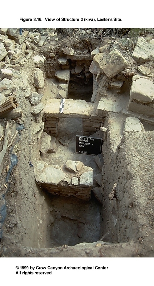
Structure 3 (Kiva)
Structure 3 is an unburned, masonry-lined kiva (Figure 8.16 and Figure 8.17). The structure was sampled by the excavation of two random 1-×-1-m units (98N/105E and 97N/107E), one judgmental 1-×-1-m unit (98N/106E), and one judgmental 1-×-2-m trench (98N/107E). Excavation in the two random units exposed sections of the upper lining wall, bench surface, bench face, and ventilation system. The judgmental excavation exposed most of Pilaster 1 and portions of the hearth and masonry deflector. Judgment unit 98N/106E was excavated only to the level of the bench surface, 60 cm below modern ground surface. This is because the unit was excavated to facilitate the excavation of the northeast corner of probability unit 98N/105E, which extended no deeper than the bench surface. The extrapolated diameter of the structure is 4.0 m, bench face to bench face.
Construction
Walls. Segments of the upper lining wall and bench face were exposed during excavations in Structure 3. The upper lining wall varies between 52 and 60 cm wide and contains a rubble core.The inside face of the upper lining wall is 79 cm long and ranges from 31 to 59 cm high above the bench surface. This face is composed of one vertical slab and several smaller rocks, which may be minimally shaped. The mortar beds are as wide as 3.5 cm. The mortar is a brown sandy clay loam containing small bits of sandstone, charcoal, and calcium carbonate flecks. No chinking was noted. The foundation below the inner face was not observable.
The observable portion of the outside face is 1.04 m long and 60 cm high. This face was constructed of one boulder and a maximum of three courses of unshaped blocks. The masonry is either semicoursed or uncoursed; the limited area exposed did not allow for a definite determination. No chinking was noted. The outside face appears to be resting on undisturbed sterile sediment; however, the poor lighting and the small size of the area observed made observation difficult.
The only bench face exposed was immediately on either side of the ventilator tunnel opening. There the bench reaches a height of 71 cm above the floor surface. The bench face is a single stone deep and ranges from 19 to 30 cm thick. The face is constructed of tabular and block sandstone rocks, most of which are pecked. The foundation of this wall is sandstone bedrock, and the wall is anchored to the bedrock with a bed of mortar 1 to 5 cm thick. The mortar beds in the remainder of the bench face are 0.5 cm to 3.5 cm wide. No chinking is visible in this section of bench face.
Roof. Pilaster 1 (Feature 4) and unburned roof fall resting on the floor (Surface 1) provided evidence of the style of roof construction in Structure 3. The stratum interpreted as roof fall is shown on the stratigraphic profile as Stratum 7 (Figure 8.18). This massive, rapidly deposited stratum contained no vegetal component, but it did contain numerous large adobe nodules and sandstone structural collapse. The deposit rested on the floor (Surface 1), with no evidence of aeolian or alluvial sediment either below it or mixed with it. For a fuller description of Stratum 7, see the Stratigraphy section below.
The pilaster is assumed to be Pilaster 1 (numbering clockwise beginning at the southern recess) of a six-pilaster, cribbed-roof support system typical for kivas in this geographic location and time period. The lack of natural deposition between roof fall and the floor (Surface 1) indicates that the roof collapsed at abandonment. Also, there is no evidence to indicate that the roof fall stratum contained a vegetal component. These two pieces of evidence suggest that the roof was dismantled, and the timbers salvaged, at abandonment.
Surface 1. Surface 1 is the floor, or occupation surface, in Structure 3 (Figure 8.19). It is composed of irregular patches of adobe applied to sandstone bedrock. The bedrock surface had probably been leveled, as was the case in Structure 1, but this was difficult to observe in the small area of floor exposed. The adobe appears only to be filling in low spots in the bedrock, but perhaps originally it was a more complete layer. The heaviest coating of adobe is in the area of the deflector, although the deflector itself is anchored directly to bedrock with a yellower, sandier mortar. A thin layer of ashy sediment coats the floor surface between the deflector and the ventilator tunnel entrance. This appears to be an organic film that accumulated during use.
Surface 1
Surface 1 is the floor used during the occupation of the structure. It is bedrock coated with patchy adobe. Several features and artifacts are associated with this surface.
Features. Several features were exposed during the excavations in Structure 3: Bench 6, the ventilator tunnel, Bench 1, Pilaster 1, the hearth, and the deflector. These are discussed in numerical order by feature number.
Feature 1 (Bench 6): Feature 1 is believed to be the sixth bench surface in this kiva, numbering clockwise from the southern recess. A small portion of Bench 6, or the southern recess, was exposed in the southeast corner of 98N/106E. Although its surface could not be defined, an in situ horizontal construction slab indicates the approximate level of the surface. In unit 97N/107E, the bench appears to have collapsed into the ventilator tunnel postoccupationally. A probable remnant of the southern recess upper lining wall was observed at the south end of the west face of 97N/107E, above the masonry of the tunnel wall.
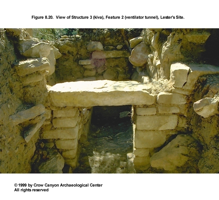
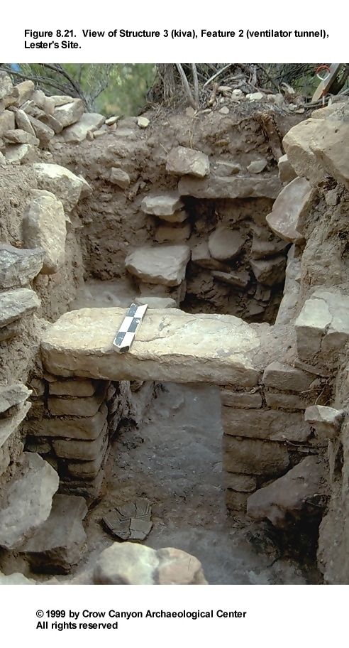
Feature 2 (Ventilator Tunnel): Feature 2 is a masonry-lined ventilator tunnel with a sloping, bedrock floor (Figure 8.17 and Figure 8.19). The sides of the tunnel opening are constructed of blocks with corners carefully pecked at right angles (Figure 8.20, Figure 8.21, and Figure 8.22). The top of the tunnel opening is composed of a large sandstone lintel slab that rests on the tops of the tunnel walls. The width of the tunnel below the lintel stone is 38 cm; the remainder of the tunnel is 42 to 50 cm wide.
The excavated portion of the tunnel is 1.2 m long. If the horizontal slab shown at the south end of the tunnel in Figure 8.17 is part of the ventilator shaft construction, then the entire tunnel may have been exposed during excavation. The masonry that lines the tunnel walls is one stone wide and composed of a variety of materials: blocky, rectangular sandstone, which is the most common; small, tabular sandstone; and a single boulder. Some of these stones have been shaped by pecking. The upper course of masonry from the east tunnel wall had collapsed into the tunnel postoccupationally.
The fill within the tunnel is illustrated in Figure 8.22. Stratum 1 is a dark brown to dark yellowish brown sandy loam containing wall rubble and charcoal flecks. This sediment was naturally deposited postoccupationally. Stratum 2 is mottled silt loam containing sandstone rubble and adobe nodules. These materials are believed to have collapsed from the tunnel walls. A thick deposit of adobe at the bottom of Stratum 2 is thought to be collapsed structural material from either the ventilator tunnel roof or the kiva roof. Loose fill beneath this adobe at the top of Stratum 3 may be rodent disturbance or could be decomposed wood from the ventilator tunnel roof. No wood remnants were recognizable, however.
Stratum 3 is a dark brown to dark yellowish brown sandy loam containing charcoal flecks, small sandstone bits, and rocks as long as 5 cm. This deposit is believed to be a layer of construction material resting on the bedrock surface. There is a lens of adobe within this deposit; in some areas in the southern two-thirds of the tunnel, the tunnel walls rest on the adobe. In the northern end of the tunnel, the walls were built on the bedrock surface. Thus, Stratum 3 was probably intended to create a level surface for the construction of the tunnel walls. This implies that the 10 degree slope of the tunnel floor is due to the natural slope of the bedrock surface, rather than to ventilator design.
Stratum 4 is a dark brown to dark yellowish brown sandy loam containing less large rubble than Stratum 1, although smaller sandstone rocks (less than 10 cm in diameter) are common. Small adobe nodules are also present. This deposit is probably construction fill associated with the construction of the ventilator tunnel, but alternatively, it could be postoccupational fill that accumulated after the south wall of the southern recess collapsed downslope and the recess surface collapsed into the ventilator tunnel.
If Stratum 4 is construction fill east of the tunnel wall, this indicates that the pit originally excavated for the tunnel was larger than the final construction and was backfilled after the masonry was constructed. There is no evidence of decomposed vegetal material in the tunnel fill, but if timbers were used in the construction of the tunnel roof, they could have been salvaged at abandonment.
Feature 3 (Bench 1): Bench 1 is the first bench surface clockwise from the southern recess. A small portion of this bench was exposed during excavations in Structure 3. The area exposed is 78 cm long and 42 to 49 cm wide. No bench surface was defined; postoccupational exposure to the elements is probably responsible for the poor preservation. The level of the bench surface, however, is assumed to approximate the top of the bench face masonry.
Feature 4 (Pilaster 1): This feature is Pilaster 1, that is, the first pilaster clockwise from the southern recess. It measures 60 cm front-to-back, 72 to 84 cm side-to-side, and reaches a height of 37 cm above the bench surface. The pilaster is constructed of shaped sandstone blocks set in reddish brown, sandy clay loam mortar. The outward faces and corners of the large blocks that form the pilasters have been intensively pecked. The interior of the construction resembles rubble more than coursed masonry. Only two courses of masonry survive; the top of the surviving construction is level with modern ground surface. Thus, the pilaster was probably taller originally, but suffered damage from postoccupational exposure.
Feature 5 (Hearth): Judgmental excavation in Structure 3 exposed a segment of the hearth (Figure 8.19 and Figure 8.23). This exposed portion measures 41 cm north-south, 44 cm east-west, and 14 cm deep. The pit was pecked into the sandstone bedrock that forms the floor of the kiva. A small, vertical sandstone slab was then mortared into place with adobe along the southwest edge of the pit. Construction mortar containing sandstone inclusions was packed into the crevice between the slab and the wall of the basin. Adobe was then applied to the bottom of the north face of the slab, to the southern half of the west wall of the basin, and to at least some of the basin floor. Adobe might have lined the entire basin originally, but exfoliated during use. Fire-reddening can be observed on the exposed sandstone in the bottom of the pit and on the adobe that lines the west wall of the pit.
The fill in the hearth is use-associated, unconsolidated ash with charcoal pieces as large as 1.5 cm in diameter. The two largest fragments were collected as tree-ring samples but were not datable. All ash was collected from the excavated portion of the hearth for flotation (three 1-liter samples) and for fine-screening. No artifacts were recovered during excavation.
Feature 6 (Deflector): A portion of a masonry deflector was exposed in the judgmental trench of Structure 3 (Figure 8.19 and Figure 8.23). The exposed portion measures 74 cm long and 30 cm wide, and it reaches a height of 60 cm above the kiva floor. The deflector is semicoursed masonry constructed of sandstone blocks and slabs. Some of the blocks and slabs are minimally shaped. The mortar beds are 1 to 10 cm thick. The mortar is a reddish brown sandy loam containing dense calcium carbonate flecks, numerous bits of sandstone as large as 1 cm in diameter, and very sparse and tiny charcoal flecks.
The deflector was set into a layer of mortar that had been applied to the bedrock surface of the kiva. The mortar extends out from the base of the deflector 5 to 10 cm to the north, 1 cm to the west, and 6 cm to the south. This mortar served to anchor the deflector to the bedrock, and it is a different color and texture than the mortar used in the masonry itself. The "anchoring" mortar is browner, sandier, and contains smaller sandstone bits than the mortar that cements the rocks together. The adobe that coated some areas of the kiva floor was applied after the deflector had been anchored to the bedrock.
The deflector is assumed to have prevented direct air flow from the ventilator tunnel to the hearth. The deflector extends too far to the east to be centered in front of the ventilator tunnel. Also, it is not parallel to the ventilator tunnel opening but is canted at a slight angle, the west end being farther north.
Artifacts. No artifacts were found in direct contact with Surface 1. The following artifacts were point-located between .5 cm and 5 cm above Surface 1 and may be associated with this surface:
-
PL 1 nonhuman bone
PL 2 chipped-stone debris (2)
PL 3 Mesa Verde Black-on-white sherd
PL 4 Pueblo III White Painted sherd
PL 5 Indeterminate Corrugated Gray sherd
PL 6 chipped-stone debris (1)
PL 7 Indeterminate Corrugated Gray sherds (2)
PL 8 Pueblo III White Painted sherd
PL 14 Mesa Verde Black-on-white sherds (7)
Pueblo III White Painted sherds (3) (all 10 sherds in PL 14 fit together)
These artifacts are probably a mixture of refuse left on the floor at abandonment and items that came to rest there during roof dismantling.
Stratigraphy
The fill in Structure 3 is postoccupationally deposited aeolian, alluvial, and colluvial deposits and structural collapse that appears to be associated with abandonment. Figure 8.18 illustrates the north-south stratigraphic profile along the 108E line. Ten sediment samples were collected from the face of this profile. The deposits will be described from modern ground surface to bedrock.
Stratum 1 is a dark yellowish brown silty sand containing decomposing organic material, sandstone bits, and sparse calcium carbonate flecks. These are recent aeolian and alluvial sediments.
Stratum 2 is a very compact, dark brown clay loam with numerous inclusions: sandstone wall fall; very coarse sand; very fine gravels; calcium carbonate flecks; some small wash lenses of yellower sand, charcoal, and very fine gravels; a few pieces of sandstone as large as 1 cm in diameter; and very sparse and tiny charcoal flecks. This is a natural, postabandonment deposit of clayey sediment mixed with a substantial amount of sandstone structural collapse. Within the stratum are some small lenses of alluvial sand and lenses of gravel. These lenses and the relatively high clay content of the stratum in general indicate that most of the sediments in this stratum were deposited alluvially.
A charcoal lens demarcates the bottom of Stratum 2. The lens extends over the top of the deflector at its north end and nearly reaches modern ground surface at its south end. The origin of this charcoal lens is unknown, but it may be associated with a charcoal lens in the upper fill of Structure 2 that is inferred to be the result of a recent use of the site.
Stratum 3 is a brown to yellowish brown sandy silt containing dense wall fall; gravels and calcium carbonate flecks are common, and charcoal flecks are present. This postabandonment deposit consists of aeolian and alluvial sediments among wall collapse rubble. The rubble may have originated from the kiva roof or from the upper lining wall of the southern recess.
Stratum 4 is a compact, brown sandy clay loam containing alluvial sand lenses, very fine gravels, and sparse calcium carbonate flecks. This is a postabandonment deposit containing aeolian sediment and material that washed into the kiva depression from the north.
Stratum 5 is a yellowish brown silt loam containing many inclusions: wall collapse rubble, a moderate number of small adobe nodules, numerous small sandstone pieces up to 3 cm in diameter, and sparse charcoal and calcium carbonate flecks. This postabandonment stratum contains a substantial amount of wall collapse that was deposited sometime after the roof collapsed.
Stratum 6 is a yellowish brown sandy clay loam containing a moderate number of inclusions: small sandstone rocks up to 5 cm long, gravel-size sandstone bits, calcium carbonate flecks, adobe nodules, and tiny charcoal flecks. These inclusions are similar to, but sparser than, the inclusions in Stratum 7. The stratum is similar to Stratum 5, which is south of the deflector, and may be the same deposit. In any event, Stratum 6 was deposited after abandonment and appears to be wall collapse.
Stratum 7 is a yellowish brown sandy clay loam containing by far the most inclusions in the profile: large sandstone rocks, rocks as small as 1 cm in diameter, sandstone gravels, calcium carbonate flecks, unburned adobe nodules as large as 4 cm in diameter, and charcoal flecks. The large sandstone rocks are structural collapse. These may be associated with the roof, or they may be collapsed materials from the upper lining wall.
Stratum 7 is consistent through the main chamber and southern recess. It is interpreted as roof fall because it contains numerous large nodules of adobe, because it is massive and homogeneous, and because it contacts the kiva floor. The roof apparently collapsed at abandonment, before any aeolian or alluvial sediment was allowed to accumulate on the floor surface. Because there is no evidence of decomposed vegetal material in this roof fall stratum, the roof was probably intentionally dismantled for the salvage of timbers.
To summarize, the fill in Structure 3 consists of unburned roof fall (deposited at abandonment), subsequent wall collapse, and aeolian, alluvial, and some colluvial sediments that then filled the remaining depression. The proximity of the kiva walls and benches to the modern ground surface, and probably to the prehistoric ground surface as well, caused this architecture to suffer exposure after abandonment.
The following artifacts were recovered from the excavated portion of the fill of Structure 3:
-
36 Indeterminate Corrugated Gray sherds
7 Pueblo III White Painted sherds
17 Late White Unpainted sherds
1 McElmo Black-on-white sherd
4 Mesa Verde Black-on-white sherds
2 nonhuman bones
62 pieces of chipped-stone debris
1 abrader
1 peckingstone (PL 1)
1 core (PL 4)
Also recovered were two halves of a stone disk or lid (PLs 2 and 3), which were in roof fall just north of the ventilator tunnel. The disk is of slate and is ground, polished, and striated. The two halves were on top of each other and probably had been pushed off of the southern recess bench surface during the natural filling of the structure.
Dating
There are no absolute dates for Structure 3. The two small tree-ring samples collected from the fill of the hearth were not datable. No archaeomagnetic dating was possible, because of the scanty amount of adobe lining the hearth. Thus, the presence of late Pueblo III pottery, the architectural style of the kiva, and the presumed contemporaneity with Structure 1 are the only means of dating Structure 3. The construction of Structure 1 has been tree-ring dated to A.D. 1270 or shortly thereafter and has been dated archaeomagnetically to A.D. 1275-1650.
Interpretations
Structure 3 is an unburned, masonry-lined kiva. Excavations in random and judgmental units exposed portions of the upper lining wall, bench surface, bench face, pilaster, southern recess, ventilator tunnel, floor surface, deflector, and hearth. The construction style and features are similar to other Pueblo III, masonry-lined, six-pilaster kivas.
The area of floor observed in this kiva varies between 1.05 m and 1.40 m below modern ground surface. This wide range is a result of the slope of modern ground surface, not the slope of the floor. The shallowness of the structure is undoubtedly a function of the depth at which sandstone bedrock was encountered during construction. The result of the shallow construction is that architecture that is protected from the elements in deeper structures was, in this case, exposed to the elements after the roof collapsed. This, and the steepness of the topography, resulted in poor preservation of the pilaster, upper lining walls in the southern recess, and all bench surfaces observed. The bench surfaces were probably a maximum of 60 cm below prehistoric ground surface, and it is likely that they eroded after abandonment.
The absence of aeolian and alluvial sediments on the floor surface indicates that the roof collapsed at abandonment, before any sediments were allowed to accumulate. The absence of substantial vegetal material in the roof fall stratum suggests that timbers were salvaged from the roofing material. The artifacts on the kiva floor appear to be incidental refuse. These three pieces of evidence suggest intentional dismantling of the roof during a leisurely abandonment.
Pit Structures (Sampling Stratum 2) Summary
The sampling of the pit structure stratum resulted in the testing of two kivas at Lester's Site. Four random 1-×-1-m units and three judgmental units were excavated in this stratum. Random units 97N/122E and 97N/124E are within Structure 1; judgmental unit 97N/123E was excavated between these two 1.9-m-deep units for excavator safety. Unit 97N/125E was one of the randomly selected units in the surface architecture stratum (Sampling Stratum 1), but it overlapped the east wall of Structure 1, and therefore is discussed with the pit structure sampling stratum.
Testing of Structure 1 resulted in the exposure of portions of the following features: the retaining wall, the upper lining wall, a pilaster, a bench, an occupation surface, a construction surface, and a remodeled hearth. Testing also resulted in the collection of 205 tree-ring samples, 90 of which were datable. The dates suggest that construction occurred in A.D. 1270 or shortly thereafter. Archaeomagnetic dating places the hottest fire prior to hearth remodeling sometime between A.D. 1275 and 1650.
Structure 1 is thought to have been intentionally burned when it was abandoned, which probably coincided with the abandonment of the site. Although a substantial number of tree-ring samples were collected from the tested portion of the structure, large-diameter timbers were absent, which suggests that even though some component of the roof burned, the larger timbers may have been salvaged first. After the burned roof collapsed, the remainder of the structure filled naturally.
Structure 3 was sampled by the excavation of random units 98N/105E and 97N/107E. Judgmental excavation in 1-×-1-m unit 98N/106E facilitated the excavation of the northeast corner of random unit 98N/105E. Judgmental testing in the 1-×-2-m trench (98N/107E) allowed access to, and sampling of, the kiva hearth. The following architecture was defined during testing in Structure 3: the upper lining wall, a pilaster, a bench, the ventilator tunnel, an occupation surface, the deflector, and the hearth. The roof is believed to have been dismantled for the salvage of timbers and to have filled naturally thereafter. No absolute dates are available for Structure 3, but the structure is assumed to be contemporaneous with Structure 1.
Courtyard (Sampling Stratum 3)
The courtyard sampling stratum surrounds the surface architecture and pit structure sampling strata; its periphery was defined by the retaining wall that bounds the architectural terrace at Lester's Site. This area of the site was probably used regularly for outdoor activities.
The courtyard stratum encompasses 149 m². Four 1-×-1-m units were randomly selected for excavation (95N/113E, 96N/113E, 90N/114E, and 102N/120E). Unit 99N/129E was erroneously excavated as a random unit as a result of a mapping error and so will be treated as a judgment unit. Testing in the courtyard exposed two segments of the main retaining wall (90N/114E, 99N/129E) and a deposit of secondary refuse (102N/120E).
Sampling Unit 90N/114E
Random unit 90N/114E is at the southern edge of the courtyard. A segment of the main retaining wall (Feature 2, Sampling Stratum 3) was exposed along the south edge of the unit. This wall is described below. First, the stratigraphy is discussed from the modern ground surface to undisturbed sterile sediment. The modern ground surface slopes down to the south 31 degrees in this unit.
Stratigraphy
Two strata were defined in 90N/114E. Stratum 1 is a brown to dark brown coarse sandy loam containing numerous large sandstone rocks (some of which are shaped), smaller sandstone rocks, sparse charcoal and adobe flecks, and a moderate number of artifacts. The large, shaped rocks probably originated from one or more surface structures to the north (see Structure 2, Sampling Stratum 1). Stratum 1 appears to be a mix of secondary refuse and a natural downslope movement of sediments that occurred postoccupationally. This deposit extended from the modern ground surface to bedrock (70 cm below the modern ground surface) in the north half of the unit; it extended to 45 cm below the modern ground surface in the south half of the unit.
Stratum 2 is a brown to dark brown sandy loam that contains finer sand than Stratum 1. Large sandstone rocks are absent from this deposit, although smaller rocks up to 15 cm in diameter are numerous. Charcoal nodules and artifacts are more common in Stratum 2 than in Stratum 1. Stratum 2 may be intentional fill associated with the construction of the retaining wall (Feature 2) that crosses the south edge of this unit. Stratum 2 reached a depth of 1.10 m below modern ground surface before bedrock was encountered.
Feature 2 (Retaining Wall)
Feature 2 is an east-west segment of retaining wall that was exposed along the south edge of random unit 90N/114E (Figure 8.4). This section of wall was constructed of large, unshaped sandstone blocks. The sediment between the rocks appears to have been naturally deposited; it is not clear if the wall was constructed with mortar or if it was dry-laid/mudded (Metzger 1988:Figure 8). It appears that there are a maximum of two courses of masonry in this segment of the wall; however, this segment is so poorly preserved that it is impossible to state the number of courses with certainty. The wall appears to be resting on a layer of rocky construction fill (see Stratum 2 description above). For additional information on the construction of the site retaining wall and a discussion of possible functions, see Feature 3 under the Midden (Sampling Stratum 5) heading and the retaining wall discussion in the Site Summary and Conclusions section.
Sampling Units 95N/113E and 96N/113E
These two adjacent random units are located midway between the two kivas in what is now a shallow drainage. Modern ground surface slopes 19 degrees down to the south in this area. No cultural features or architecture were defined in either of these units. A stratigraphic profile (Figure 8.24) of the west faces of these units and a description of the fill are presented in this section. The strata are described from the modern ground surface to bedrock.
Stratum 1 consists of 5 to 20 cm of brown sandy silt containing abundant sandstone (ranging from gravel to boulders), charcoal flecks, and small adobe nodules. This deposit appears to be postoccupational alluvial sediments and structural rubble from upslope.
The next 35 to 50 cm is Stratum 2, a brown sandy loam containing inclusions of charcoal and calcium carbonate flecks, much less and much smaller sandstone rubble, and fewer artifacts than Stratum 1. This stratum contains distinct lenses of clay, sand, gravel, and adobe. The clay, sand, and gravel are clearly alluvial deposits, but the origin of the adobe is unclear. It is possible that the layer of adobe is a prepared surface. The deposit is of fairly uniform thickness and is more continuous than is typical of wash lenses. It also contains few inclusions or the foreign material that one might expect if the adobe had been "washed" down from a collapsing surface structure or kiva upslope. However, unlike prepared surfaces, which tend to be more-or-less level, this deposit slopes 30 cm down to the south over a distance of about 2 m. Also, very thin laminae give the adobe the appearance of having been deposited alluvially. Given the limited amount of data available, the best guess is that Stratum 2 was deposited postoccupationally, and that the adobe lens is naturally redeposited structural material from the decomposing kiva. If this is the case, however, it indicates that runoff moving down this drainage was slowed enough to allow fine-grained adobe to settle out. This suggests that the main east-west retaining wall to the south (Feature 2) was tall enough to be controlling erosion.
Stratum 3 consists of 2 to 26 cm of brown sandy loam containing sandstone rocks 2 to 10 cm in diameter, charcoal and calcium carbonate flecks, and some artifacts. Cultural material continues to the bottom of this stratum, which is bedrock. This suggests that bedrock was exposed during the occupation of the site and that Stratum 3 may be material that accumulated during site use.
Sampling Unit 102N/120E
This randomly selected unit abuts the cliff face north of Structure 1 (kiva) and is not a full 1-×-1-m square. At modern ground surface, the east and west edges of the unit measure 32 cm and 55 cm north-south, respectively. The ground surface slopes 22 degrees down to the southeast. Secondary refuse deposits, possibly associated with Structure 2 (surface room) to the northwest, were recorded. All material described below has been affected adversely by roots growing along the cliff face. The stratigraphy is described from the modern ground surface to bedrock (Figure 8.25).
Stratum 1 is a brown to dark brown silty sand containing flecks of calcium carbonate and a variety of sandstone rocks (everything from rubble down to pebble-size stones). Stratum 1 is aeolian, alluvial, and colluvial, with material from the latter two processes coming downslope from the west. This is the most recent, postabandonment deposit.
Stratum 2 is a brown to dark brown sandy silt containing a few flecks of calcium carbonate and sandstone rocks ranging from building-block to pebble-size stones. It is siltier and slightly more orange than Stratum 1; the color appears to be a result of a higher adobe content. Stratum 2 thus appears to be a postabandonment deposit of structural collapse from Structure 2 (surface room), located upslope to the west and northwest.
Stratum 3 is a yellowish brown silty sand containing abundant calcium carbonate flecks, numerous sandstone pebbles, and sparse charcoal flecks. The absence of sandstone rubble indicates that this material was deposited before any of the wall collapsed. Calcium carbonate naturally occurs only subsurface at Lester's Site. The dense carbonate flecks in Stratum 3 indicates that this material originated subsurface and probably was brought to prehistoric ground surface during the excavation of the pit for Structure 1 (kiva). There is evidence that this material was then used in roof construction (see the stratigraphic profile descriptions of Structures 1 and 2). One interpretation is that Stratum 3 was the initial postabandonment deposit, resulting from the deterioration and collapse of the Structure 2 (surface room) roof. It is also possible that this stratum is associated with roof construction for Structure 1 (kiva) to the south.
Stratum 4 consists of a series of ash (dark gray), adobe (reddish brown), and calcium carbonate (very pale brown) lenses. The ash contains charcoal pieces up to 2 cm in diameter. Some small sandstone gravels are contained within the calcium carbonate, and the adobe contains charcoal flecks. The absence of mixing and alluvial lensing, the presence of very abrupt boundaries, and the integrity of the ash deposits clearly indicate that these lenses are undisturbed secondary refuse. The ash could be from a fire pit inside Structure 2 or from the hearth in Structure 1 (kiva) to the south. Although no fire pit was exposed in Structure 2, a thin, gray film on the adobe surface is thought to be ash residue from a fire pit in the unexcavated portion of that structure. Four 1-liter samples of ash were collected for flotation; the remainder of the ash was collected for fine-screening.
The origins of the adobe and the calcium carbonate lenses are more difficult to interpret. The adobe may be from whatever hearth the ash is from, but this is a lot of adobe to be the result of exfoliation during use. The calcium carbonate is obviously redeposited sterile material, possibly deposited here when the pit for Structure 1 (kiva) was being excavated.
Stratum 5 is a dark yellowish brown, medium-grained silty sand containing charcoal flecks and decomposing sandstone. This sediment continues down into the crevices in the decomposing sandstone. The origin of this material is unknown, but it was deposited during the occupation of the site. This stratum may be sediment that was deposited naturally early in the site occupation.
To summarize, random unit 102N/120E has both natural and cultural deposits. Stratum 5 appears to be material that was naturally deposited during the occupation of the site. Stratum 4 is a series of lenses of secondary refuse. Stratum 3 may be the initial postabandonment deposit, and it seems to have originated from the roof of Structure 2 upslope. Strata 2 and 1 are probably postabandonment wall collapse, also from Structure 2.
Sampling Unit 99N/129E
Due to a mapping error, this unit was erroneously excavated as a random unit. It is now treated as a judgment unit. It is near the east edge of the site, and a north-south segment of the main retaining wall was exposed in it (Feature 1, Sampling Stratum 3). Modern ground surface slopes 9 degrees down to the south in this unit. The fill in this unit consists of 20 cm (east edge of unit) to 40 cm (west edge of unit) of naturally deposited postabandonment brown sandy loam containing sparse sandstone rubble, charcoal flecks, and few artifacts.
Feature 1 (Retaining Wall)
Feature 1 is a segment of the main retaining wall exposed in unit 99N/129E (Figure 8.26). This segment is 1.0 m long, 52 cm wide, and a maximum of 32 cm high. The double-coursed wall is constructed of one large, unshaped block (85 × 35 × 28 cm) and smaller rocks, some of which are shaped. Only one vertical course remains intact. The large block was visible on the modern ground surface prior to excavation. The wall rests on top of either a subsurface sandstone boulder or bedrock. The sediment between the rocks appears to have been deposited naturally after the site was abandoned, so the mortar that originally cemented the wall together probably eroded away and was replaced with natural sediments.
This section of the wall is on a relatively level area of the site (9 degree slope) and might more accurately be considered an enclosing wall than a retaining wall. However, this is a section of the same construction that clearly functioned as a retaining wall across most of the site (Figure 8.4). This segment of the wall might have served to define the site area, or it might have helped divert runoff away from Structure 1 (kiva), located 3 m to the west. For additional information on the construction of the main site retaining wall, and a discussion of possible functions, see Feature 3 under the Midden (Sampling Stratum 5) heading and the discussion of the retaining wall in the Site Summary and Conclusions section.
Courtyard (Sampling Stratum 3) Summary
Testing of the courtyard sampling stratum was accomplished with the excavation of four random (90N/114E, 95N/113E, 96N/113E, and 102N/120E) and one judgmental (99N/129E) 1-×-1-m units. The excavation of these units resulted in the exposure of two segments of the main retaining wall at the site, the definition of a possible courtyard surface, and the sampling of some secondary refuse that is probably associated with Structure 2 (alcove room).
No absolute dates are available for the courtyard area. However, the pottery recovered and the stratigraphy observed indicate that the architecture and secondary refuse encountered are contemporaneous with the cultural material on the remainder of the site. The only absolute dates obtained for Lester's Site are reported and discussed under Structure 1 (Sampling Stratum 2).
Inner Periphery (Sampling Stratum 4)
The inner periphery sampling stratum is a narrow strip that surrounds the courtyard (Sampling Stratum 3) and the midden (Sampling Stratum 5). This stratum encompasses 179 m². Six randomly selected 1-×-1-m units were excavated (94N/100E, 92N/101E, 93N/102E, 82N/105E, 78N/120E, and 86N/131E). No judgmental pits were excavated in this stratum. A segment of the main site retaining wall (Feature 1) was exposed in unit 93N/102E. No other features or architecture were encountered during excavations in Sampling Stratum 4. Unit 78N/120E contained a large number of artifacts and probably should have been included in the midden stratum.
Sampling Unit 94N/100E
Unit 94N/100E is the westernmost excavation pit at Lester's Site. A large bedrock boulder occupies the northern two-thirds of this random unit. The remainder of the pit contains 10 to 40 cm of brown sandy sediments and few artifacts. Modern ground surface slopes 27 degrees down to the south in this unit. The bottom of the cultural deposits was defined by the exposure of the bedrock boulder across the entire unit.
Sampling Unit 92N/101E
Unit 92N/101E is also near the west edge of the site. The cultural deposits in this unit rest on a bedrock boulder. At modern ground surface, this boulder is exposed in the southeastern one-third of the unit. Modern ground surface slopes 27 degrees down to the south in this unit. Cultural deposits reach a depth of 40 cm below modern ground surface; this occurs in the northwest corner of the unit. The sediments consist of a pale brown to brown, coarse sandy loam containing unmodified sandstone, sparse charcoal flecks, and few artifacts.
Sampling Unit 93N/102E
A segment of the main site retaining wall (Feature 1) was visible on the modern ground surface in this unit. The observable stratigraphy is addressed first, followed by a description of the feature. Modern ground surface slopes 27 degrees down to the south in this unit.
The fill is composed of 5 cm (southeast corner) to 34 cm (north edge) of brown sandy loam, with sandstone inclusions measuring from 1 cm in diameter to a block 40 × 20 × 10 cm. Many of the large stones are wall fall from the retaining wall, although some of the stones also may be wall fall from Structure 3 (kiva) or from (undefined) surface rooms upslope. The bottom of the unit was defined by bedrock.
Feature 1 (Retaining Wall)
Feature 1 of Sampling Stratum 4 is another segment of the same main site retaining wall that is exposed in units 90N/114E and 99N/129E (in Sampling Stratum 3) and in unit 91N/126E (in Sampling Stratum 5). This segment is poorly preserved and has mostly collapsed downslope; however, the wall is visible on modern ground surface. The wall is a maximum of two courses high. Beneath these courses is smaller rubble that might be intentional fill associated with wall construction. No mortar was observed in the wall.
Within unit 93N/102E, the retaining wall is beneath a boulder overhang. Just outside the excavation unit, the east end of this segment of wall abuts the boulder, and the west end curves northward (Figure 8.4). The purpose of this wall appears to be to define space as well as to stabilize the slope. For more information on the construction of the main site retaining wall and a discussion of possible functions, see Feature 3 under the Midden (Sampling Stratum 5) heading and the review of this feature in the Site Summary and Conclusions section.
Sampling Unit 82N/105E
Test pit 82N/105E is just southwest of the midden. Four strata were defined in this unit; they are described from the modern ground surface to undisturbed sterile sediment. The modern ground surface slopes 24 degrees down to the south in this unit.
Stratum 1 is 18 to 24 cm of dark yellowish brown sandy loam containing very sparse charcoal flecks, a moderate number of artifacts, and abundant sandstone. The deposit appears to be postabandonment slope wash.
Stratum 2 is 20 to 40 cm of dark brown to very dark brown fine sandy loam. Artifacts, pea-size gravel, and charcoal flecks are common, and sandstone is abundant. This material is probably secondary refuse deposited during the occupation of the site, although the orientation of the sandstone (parallel to the bedding planes) suggests that the material moved naturally down the slope at least a short distance.
Stratum 3 is 7 to 20 cm of strong brown fine sandy loam containing small pieces of sandstone and calcium carbonate nodules. This deposit is similar to the undisturbed sterile sediment observed in other test pits on the site.
Five to 20 cm of Stratum 4 was removed at the bottom of this unit. It consisted of pink to reddish yellow caliche containing no cultural material. Excavation in this test pit ended at 62 to 72 cm below the modern ground surface.
Sampling Unit 78N/120E
This unit contained a very high artifact density, and thus ideally would have been included in the midden sampling stratum rather than in the inner periphery sampling stratum. Cultural deposits extend as much as 38 cm below the modern ground surface. The ground surface slopes down 22 degrees to the south. The three strata defined are described from the modern ground surface to undisturbed sterile sediment.
Stratum 1 is 10 cm of brown sandy silt containing some sandstone rocks as long as 10 cm, some calcium carbonate flecks, and numerous sandstone gravels and artifacts. This stratum appears to have formed as the result of postoccupational downslope erosion.
Stratum 2 is 25 to 29 cm of gray brown sandy loam containing numerous pieces of sandstone up to 20 cm in length, sandstone gravel, calcium carbonate flecks, and many artifacts. A complete, side-notched projectile point and a pendant blank with a partly drilled hole were among the artifacts recovered from Stratum 2. This deposit is probably secondary refuse that crept a short distance downslope into this location postoccupationally.
Fifteen cm of Stratum 3 was exposed; it consists of a reddish brown sandy loam with sandstone, decomposing sandstone, and calcium carbonate flecks. Conglomerate sandstone defined the base of Stratum 3 in approximately one-half of the unit. This sediment is apparently sterile; the top of the deposit may have been the prehistoric ground surface when occupation of the site began.
Sampling Unit 86N/131E
Test pit 86N/131E is near the east edge of the site, at the base of a boulder that separates the talus-slope midden from the upslope architecture terrace. The boulder occupies the northwestern two-thirds of the unit. The modern ground surface slopes down approximately 7 degrees to the south. Three strata were defined in the portion of the test pit not taken up by the boulder; these are described from the modern ground surface down to sterile sediment.
Stratum 1 is 8 to 15 cm of brown sandy loam. This sediment appears to have been deposited postoccupationally. Stratum 2 is 3 to 6 cm of loosely compacted grayish brown sediment that may be secondary refuse. Stratum 3 consists of a very compact, sterile, red brown sediment. Excavation continued 5 cm into this deposit. The top of Stratum 3 may have been the prehistoric ground surface when occupation of the site began.
Inner Periphery (Sampling Stratum 4) Summary
The inner periphery sampling stratum is a narrow area surrounding the main cultural units at Lester's Site. Six 1-×-1-m units were randomly selected to sample this area. Excavations in one of these units (93N/102E) exposed a segment of the main site retaining wall. The remainder of the pits contained the low artifact density expected in this stratum, with the exception of unit 78N/120E, which contained enough artifacts and stained sediment that it probably should have been assigned to the midden sampling stratum originally.
Midden (Sampling Stratum 5, Nonstructure 1)
The midden encompasses 288 m² and was sampled by excavating 12 randomly selected 1-×-1-m units:
-
79N/114E 80N/109E 80N/112E 81N/112E
81N/122E 83N/130E 84N/126E 85N/105E
85N/122E 86N/116E 90N/123E 91N/126E
The secondary refuse deposits in these random test pits yielded many artifacts. Also, four features were defined: Feature 1 (pit), Feature 2 (burial), Feature 3 (retaining wall), and Feature 4 (structure wall). A small, irregular judgmental pit was excavated adjacent to the west edge of unit 91N/126E to allow complete exposure of the burial, Feature 2 (Figure 8.27). Data for all but two of the midden units excavated can be found in Table 8.2. Test pits 81N/112E and 91N/126E will be discussed more fully below, as these units contain features.
Sampling Unit 81N/112E
Test pit 81N/112E is in the south-central area of the midden and contains a pit feature (Feature 1). Feature 1 occupies the west half of 81N/112E. The stratigraphy in the east half of the unit consists of 15 to 25 cm of brown sandy loam with charcoal flecks. This material is a combination of secondary refuse and slopewash, and it rests on sterile sediment, which in this area consists of a reddish brown coarse sandy loam. Modern ground surface slopes down 10 degrees to the south-southeast in this unit.
Feature 1 (Pit)
Feature 1 occupies the west half of unit 81N/112E. The inferred length of the pit is 108 cm north-south; the width is unknown. The excavated portion of the pit reaches a depth of 38 cm. The pit was excavated into sterile (a reddish brown coarse sandy loam) and contains two strata. Stratum 1 is a brown to dark brown sandy silt containing artifacts and charcoal flecks. Stratum 2 is redder and contains fewer artifacts and less charcoal. Both deposits are probably midden slopewash. The following artifacts were recovered from the fill:
-
1 Mesa Verde Black-on-white sherd
5 Pueblo III White Painted sherds
14 Late White Unpainted sherds
17 Indeterminate Corrugated Gray sherds
1 Indeterminate Plain Gray sherd
1 Late White Unpainted modified sherd
21 pieces of chipped-stone debris
nonhuman bone
green clay
The pit is amorphous in plan and profile, and only the north wall was clearly defined. The southeast area of wall had been damaged by a large juniper tree. Despite the irregular shape, this pit does appear to have cultural origins. The function of this feature, however, is unknown.
Sampling Unit 91N/126E
Test pit 91N/126E is located at the northeast edge of the midden. Three features (a burial, a portion of the retaining wall, and a portion of a structure wall) were recorded in this unit (Figure 8.27). The segment of retaining wall (Feature 3) was exposed along the north edge of the unit; the structure wall (Feature 4) occupies the east half of the unit. The burial (Feature 2) is at the junction of these two walls. The stratigraphy in the portion of the unit not occupied by these features is described from the modern ground surface down to sterile sediment; feature descriptions follow.
Stratigraphy
The fill in unit 91N/126E consists of three strata. Stratum 1 is a mottled, brown to dark brown sandy to silty loam containing charcoal flecks, sandstone rubble, unburned adobe nodules, and a moderate to high number of artifacts. This deposit is believed to be refuse discarded during the occupation of the site.
Stratum 2 is a yellowish brown sandy loam containing abundant inclusions of unburned adobe and fist-size and smaller sandstone rocks. Charcoal is present, but it is sparser than in Stratum 1. Stratum 2 is interpreted as intentional fill associated with the construction of Feature 3 (retaining wall).
Stratum 3 is adobe (brown to strong brown silt loam to clay loam) containing small pockets of ash, some charcoal flecks, and a few artifacts. The deposit is thickest near the walls; it thins and disappears to the south. The adobe rests on bedrock. Like Stratum 2, this material is thought to be construction material associated with the building of the walls. Wall construction is described in more detail under the appropriate feature headings below.
Feature 2 (Burial 1)
Feature 2, Burial 1, is the nearly complete articulated skeleton of a young child, recovered from Stratum 1 in 91N/126E (Figure 8.28). The age could not be determined in the field. The body was interred at the junction of the main site retaining wall (to the north), and the wall of an undefined surface structure (to the east). The west end of the body, including the upper torso and cranium, were beneath a boulder overhang. The uppermost few vertebrae and the cranium were outside unit 91N/126E, so a small, irregular judgment unit approximately 60 cm north-south by 17 cm east-west was excavated adjacent to the random unit in order to expose the entire burial (Figure 8.27).
The body was positioned on its left side; its arms were extended, and the knees were semiflexed. The cranium was grid west of the body, and faced grid north. In this position, the body measured 70 cm long and 24 cm wide, and it extended 25 cm from the top of the knees (highest elevation) to beneath the cranium (lowest elevation).
The original length of the body was distorted somewhat by a sandstone slab that rested on the upper body. The slab measured 27 cm long and 15 cm wide and rested directly on the cranium. The slab is believed to have been placed on the body as part of the interment. Beneath the slab were the cranium, the upper 10 vertebrae, one right rib, and the right scapula and clavicle. The weight of the slab apparently had caused the upper body to subside after interment, which caused that portion of the body ultimately to rest at a lower elevation than the remainder of the body. This action also caused the torso and upper body to separate from the pelvis somewhat.
The bone was generally well preserved and not overly friable. However, the distal end of the left femur and the proximal ends of the right tibia and fibula splintered when the weight of the sediment above the body pressed these bones against a sandstone rock that was beneath them.
It is assumed that the body was interred into a burial pit, given the articulation of the skeleton. However, no amount of scrutiny resulted in the detection of a pit boundary; the fill between the bones was identical to the fill elsewhere in Stratum 1. The pit was apparently excavated into the secondary refuse, and the same material was then used to cover the body and finish filling the burial pit. The bottom of the pit was the top of undisturbed Stratum 2, which is the clean construction fill that the retaining wall (Feature 3) rests on (Figure 8.29).
Most of the artifacts in proximity to the body appeared to be incidental refuse that happened to be in the secondary refuse that the body was interred into. One high-input artifact beneath the cranium, however, was probably intentionally placed with the body. This artifact (PL 18) is a bead fashioned from a section of a bird long bone, and perforated at one end. The other artifacts from the burial area are the following: Pueblo III White Painted sherds (N = 4), Late White Unpainted sherds (N = 3), Indeterminate Corrugated Gray sherds (N = 9), and chipped-stone debris (N = 18, including one edge-damaged flake).
Two samples were collected from the burial. A flotation sample (PL 16) was taken from the abdominal area, and a pollen sample (PL 17) was taken from among the ribs. These samples have not been analyzed.
In summary, after at least 25 cm of secondary refuse had accumulated during the occupation of the site, the body of a small child was interred into an undefinable pit at the junction of two walls. A perforated long-bone bead was placed beneath the back of the skull. A sandstone slab was placed on top of the head and upper torso, and the pit was backfilled with secondary refuse. Additional data are presented in Chapter 19 of this volume.
Feature 3 (Retaining Wall)
Feature 3 is a segment of the main site retaining wall that separates the courtyard from the midden at Lester's Site. This segment is observable at the north edge of 91N/126E (Figure 8.27, Figure 8.28, and Figure 8.29). In this unit, the wall was recognizable prior to excavation, but its full depth was not observable until excavation of the unit was completed.
This segment of the retaining wall reaches a maximum height of 150 cm; 10 vertical courses are present. Within the excavation unit, 30 cm of width is observable. The wall is semicoursed and constructed of large, unshaped or minimally shaped sandstone blocks. The cross section is not observable, but it is probably more substantial than single stone (that is, either double stone or compound). The west end of this segment of wall abuts a boulder just outside the excavation unit (Figure 8.27). East of the unit, the wall apparently serves as the north wall of the undefined structure for which Feature 4 is the west wall.
The construction of this retaining wall was a complex process that is not fully understood. The base of the wall rests on a foundation of bedrock in some places, on construction fill in other places (Figure 8.29), and on the lowermost two courses of Feature 4 (structure wall) in yet another place. The construction of these walls will be described as well as possible given the limited data available.
Prior to the construction of these two walls, bedrock was either already exposed naturally, or it was cleared of sediment to prepare for construction. One to two courses of the structure wall (Feature 4) were then built on bedrock. These two courses of the structure wall extend beneath the retaining wall, and thus predate that wall. A deposit of adobe (Stratum 3) at the base of the walls either accumulated incidentally during construction or, more likely, was placed there to anchor the structure wall to the bedrock surface. Then Stratum 2 was deposited to help create a level foundation for the retaining wall (Feature 3). The remaining courses of the retaining wall were then constructed. After that wall was complete, the remainder of the structure wall was built; this portion of the wall abuts the retaining wall.
This odd construction sequence may be explained as follows. The initial two courses of structure wall might have been built prior to the construction of the retaining wall in order to help stabilize and contain the construction fill (Stratum 2) that could then be deposited as retaining wall foundation. This would explain why only two courses of the structure wall were built initially, and then the remainder of the retaining wall was constructed.
The original height of this wall is unknown. At the time of construction, this wall might have been completely freestanding, or it might have faced sediments of the higher terrain immediately to the north. In either case, it would have served to reduce erosion of the slope on which the architecture of the site was constructed. It is probable that at least a portion of its height was originally freestanding. Fill could then have been intentionally added behind the wall upslope, or sediment could have been allowed to accumulate naturally behind it, thus creating a more level terrace for architectural construction and for daily activities.
Feature 4 (Structure Wall)
Feature 4 in Sampling Stratum 5 is a 1-m-long segment of wall that is apparently the west wall of an undefined, isolated, D-shaped or rectangular surface structure (Figure 8.27). This undefined structure was recognized on modern ground surface as a small, fairly level area bounded on the southeast by visible wall. This area was assigned to Sampling Stratum 1 (surface architecture); no randomly selected units were within this area. Because the portion of wall that subsequently was within unit 91N/126E was not visible from modern ground surface, the Sampling Stratum 1 boundary was placed a few meters too far to the east to coincide with the actual structure boundary. The north wall of this structure appears to be the main site retaining wall.
The Feature 4 wall is a maximum of 116 cm high and 58 cm wide. Seven vertical courses survive. The construction is massive--either compound with core or double-stone with core in cross section. The outside facing stones are large. Approximately 70 percent of the outside faces are pecked, and most of the remainder were minimally shaped by flaking. One shaped stone in the bottom course measures 70 × 30 cm and might have been a boulder from the immediate area that was incorporated into the wall. Most mortar joints are less than 3 cm thick; those that are thicker are chinked with sandstone spalls. The interior of the wall is composed of smaller sandstone rocks and sediment (not adobe).
The portion of the structure wall examined rests on bedrock. The bottom two courses extend beneath the retaining wall to the north (Feature 3). The upper four courses abut that same wall. The above discussion of Feature 3 construction includes a description of Feature 4 construction.
Midden (Sampling Stratum 5, Nonstructure 1) Summary
The midden was sampled with 12 randomly selected 1-×-1-m test pits. One small judgment pit was excavated in order to fully expose a burial found in unit 91N/126E. The slope of the modern ground surface ranged between 10 and 34 degrees. Two of the random test pits contained one stratum (less than 25 cm deep) of postoccupational slopewash atop bedrock. One pit contained one stratum of postoccupational slopewash atop undisturbed sterile sediment. In two units, there was one stratum of midden that had "crept" downslope, on top of undisturbed sterile sediment. Five of the midden units contained a stratum of postoccupational wash, a stratum of intact midden, and a stratum of undisturbed sterile sediment. The overall depth of the units ranged from 10 to 85 cm.
Four features were recorded in the midden: a pit, a primary interment of a child, a segment of the main site retaining wall, and a section of structure wall. Artifacts recovered from the midden sampling stratum are listed in tables at the end of this chapter.
Outer Periphery (Sampling Stratum 6)
This outer periphery sampling stratum is a rectangular block 12 m north-south by 30 m east-west that is immediately south of the inner periphery (Sampling Stratum 4). This stratum was designated in order to sample an area that contains artifacts but is peripheral to the main site area and also to sample the amount of downslope movement of artifacts. This stratum contains 360 m². Five randomly selected 1-×-1-m units were excavated to sample this stratum (76N/106E, 67N/113E, 72N/118E, 68N/124E, and 70N/126E). No judgment units were excavated in Sampling Stratum 6. No features were encountered.
Sampling Units 76N/106E, 67N/113E, and 72N/118E
These three sampling units contained one stratum of slopewash, and will be described together. The amount and direction of slope at the modern ground surface for units 76N/106E, 67N/113E, and 72N/118E is 14 degrees south, 15 degrees south, and 23 degrees southwest, respectively. The one stratum present in all three units consists of a brown to reddish brown sandy loam with sandstone inclusions. This stratum of slopewash is 15 to 26 cm thick and rests on undisturbed sterile sediment.
Sampling Unit 68N/124E
The modern ground surface slopes 15 degrees to the south in unit 68N/124E. Three strata were observed during excavation of this unit. Stratum 1 is 20 cm of dark brown fine sandy loam containing sandstone and flecks of charcoal and calcium carbonate. Stratum 2 is 19 to 32 cm of yellowish brown fine sandy loam with the same inclusions as Stratum 1. Stratum 3 is 8 to 48 cm of yellowish brown silt loam containing the same inclusions as the upper strata. Stratum 3 ends on bedrock at 93 cm below the modern ground surface.
The depth and texture of the deposits in this unit appear to be related to the rock alignment directly downslope (Figure 8.2). This rock alignment might have served to form or stabilize an agricultural terrace. Stratum 3 is interpreted as possible arroyo fill, whereas Stratum 2 is thought to be slopewash that accumulated behind the rock alignment during the occupation of the site. Stratum 1 would then be postoccupational slopewash. Five pollen samples were collected from this unit to help determine whether test pits 68N/124E and 70N/126E were, in fact, located on an agricultural terrace. These samples have not been analyzed.
Sampling Unit 70N/126E
The slope of the modern ground surface in unit 70N/126E is 17 degrees to the south. Three strata were recorded. Stratum 1 is 20 cm of yellowish brown fine sand with sandstone inclusions. Stratum 2 consists of 17 to 24 cm of brown to dark brown coarse sandy loam with calcium carbonate and numerous sandstone gravel inclusions. Stratum 3 is the C-horizon shale bedrock. Excavations reached a maximum depth of 44 cm below modern ground surface.
As with unit 68N/124E, the deposits in this unit seem to have been affected by the presence of the rock alignment directly downslope. Stratum 1 is recent slopewash; Stratum 2 appears to be sediment that accumulated during the occupation of the site. Thus, the shale bedrock might have been exposed at the beginning of site occupation.
Outer Periphery (Sampling Stratum 6) Summary
Five randomly selected 1-×-1-m pits were excavated to test this sampling stratum. This area contains a limited number of artifacts, most of which probably moved downslope into this area after the site was abandoned. Three of the test pits contained one shallow stratum of slopewash; the other two units had more complex stratigraphy. Those two units were upslope from a rock alignment (recorded as Feature 1 in Sampling Stratum 7), which apparently caused additional sediments to be deposited in that area.
Outer Periphery (Sampling Strata 7 and 8)
The descriptions and discussions of Sampling Strata 7 and 8 are combined in this section, as these strata are at the outermost reaches of the artifact scatter at Lester's Site (Figure 8.3). Sampling Stratum 7 extends from the edge of Sampling Stratum 6 south to Sand Creek. It is 30 m wide and 25 m long and encompasses 750 1-×-1-m units. Five of these units were randomly selected for excavation (58N/102E, 57N/105E, 47N/108E, 41N/108E, and 51N/129E). No judgment units were excavated in this sampling stratum. One feature, a rock alignment, was recorded. This feature is not within an excavation unit but is visible on the modern ground surface.
Sampling Stratum 8 consists of two north-south strips that extend the full length of the site and are on either side of the sampling strata already discussed. These areas encompass the east and west edges of the artifact scatter. Sampling Stratum 8 contains 840 m². Five 1-×-1-m units were randomly selected for excavation (98N/133E, 94N/135E, 91N/134E, 47N/134E, and 46N/138E). None of the units selected were in the western strip of this sampling stratum. No judgment units were excavated. No features were recorded in Sampling Stratum 8.
A summary of the stratigraphic data for the 10 test pits in Sampling Strata 7 and 8 is presented first. A discussion of Feature 1 follows.
Stratigraphy
Although the test pits excavated in Sampling Strata 7 and 8 were similar in some respects, there was variation as well. The slope of the modern ground surface varies widely. The degree of slope ranges between 8 and 29 degrees; the direction of slope varies from southeast to south to west. The one stratum containing cultural material (slopewash) is 5 to 33 cm thick. This sediment varies from a brown silt loam to a brown sand and contains sandstone inclusions as well as artifacts. The three upslope units (98N/133E, 94N/135E, and 91N/134E) also contained charcoal flecks. The southeasternmost unit (46N/138E) contained only angular debris (all from the Morrison Formation). Slopewash generally rested on top of sterile deposits of red brown silty clay loam to sandy loam; in one unit (98N/133E), bedrock was encountered.
Feature 1 (Rock Alignment)
This rock alignment was not exposed by excavation but was recorded from observations made at modern ground surface. The feature runs grid east-west, or parallel to the slope contour, approximately 15 m grid south of the edge of the midden (Figure 8.2). To form the alignment, large, unshaped sandstone rocks were placed side by side across the slope. The visible portion of the feature is 7.4 m long and is on the east side of a shallow drainage. A maximum of two vertical courses are visible; additional courses may exist below the modern ground surface. This alignment may have been constructed to control erosion, to accumulate sediment, or both. If the purpose was to accumulate sediment, the ultimate objective may have been the formation of an agricultural terrace (also see discussion of units 68N/124E and 70N/126E, above). Alternatively, the feature could have been a check dam for floodwater irrigation.
Outer Periphery (Sampling Strata 7 and 8) Summary
These two outer periphery sampling strata were tested by excavating five randomly selected units in each stratum. Because the units are scattered both north-south and east-west across the site, there is a substantial amount of variation in the stratigraphy and in the depth of cultural deposits. Artifacts are present as far as 35 m south of the south edge of the midden, and most probably arrived this far south as a result of postabandonment downslope movement. Only units 98N/133E and 46N/138E contained no artifacts.
The presence of a rock alignment in Sampling Stratum 7 indicates that modification of the natural landscape on Lester's Site was occurring a substantial distance from the habitation area. This feature caused slopewash sediments to accumulate upslope from the feature (in Sampling Stratum 6).
Lester's Site Artifacts
Artifacts recovered during testing at Lester's Site are reported in tables at the end of this chapter (Table 8.3, Table 8.4, Table 8.5, Table 8.6, and Table 8.7). The quantity and variety of artifacts suggest that the site was used as a year-round habitation. The pottery assemblage corroborates the tree-ring data, which indicates that the site was occupied during the last half of the A.D. 1200s.
The pottery recovered from the site dates almost exclusively to the Pueblo III period. The few earlier sherds consist of the following: one Mancos Gray sherd, one Early White Painted sherd, two Early White Unpainted sherds, four Mancos Black-on-white sherds, and two Pueblo II White Painted sherds. These sherds make up less than 0.2 of one percent of the site total and are too few to have resulted from an earlier occupation of Lester's Site. Decorated white ware sherds dating to the Pueblo III period include 17 McElmo Black-on-white sherds, 140 Mesa Verde Black-on-white sherds, and 415 Pueblo III White Painted sherds. These Pueblo III decorated white ware sherds compose 98.5 percent of the total decorated white wares from the site. Only one pre-Pueblo III gray ware sherd was recovered--a Mancos Gray sherd. Thus, the pottery assemblage suggests that Lester's Site is the result of one occupation that occurred during the Pueblo III period.
A wide variety of other artifacts were also collected during testing. Ground-stone tools, chipped-stone tools, chipped-stone debris, human bone, modified and unmodified nonhuman bone, modified sherds, pendants, mineral samples, eggshell, and gizzard stones were recovered. More specifically, the following complete and fragmentary tools were collected:
-
15 metates
10 manos
4 abraders
3 hammerstones
6 peckingstones
6 axes
1 maul
1 polishing stone
7 projectile points
4 bifaces
21 cores
14 modified flakes
2 other chipped-stone tools
5 other modified stones
3 awls
Other artifacts recovered were three bone tubes, 23 modified sherds, two pendants, two pendant blanks, one slate disk, unmodified nonhuman bone, two eggshell fragments, and one gizzard stone. The quantity and variety of artifacts suggest that a wide range of activities were engaged in by the inhabitants of the site for a substantial period of time. Some of these activities included procurement, storage, preparation, and consumption of vegetal and meat resources; stone tool manufacture and repair; pottery, ornament, and clothing production; and architectural construction.
Thirteen artifacts from Lester's Site (less than 0.1 percent of the total) were identified as being of nonlocal origin or material. Six sherds, or 0.1 percent of the total sherds, are nonlocal. Two of these are Tsegi Orange Ware, two are Wingate Black-on-red, and two are unknown White Mountain Red Ware. These Pueblo III wares were manufactured in northeastern Arizona, and their presence on the site indicates some interaction with that area. Other materials of nonlocal origin are one Washington Pass projectile point, one nonlocal chert/siltstone projectile point, and five pieces of Washington Pass chipped-stone debris. Washington Pass is in northwestern New Mexico, west of Chaco Canyon. Thus, although few items of nonlocal origin were recovered from Lester's Site, some interaction with northeastern Arizona and northwestern New Mexico is suggested by the presence of these items.
Site Summary and Conclusions
Lester's Site is a small cliff-face/talus-slope habitation located just below the north rim of Sand Canyon, 550 m west of the canyon head. The site is believed to have been occupied in the last half of the A.D. 1200s, based on A.D. 1270s tree-ring dates and on an archaeomagnetic date range of A.D. 1275-1650, all from Structure 1 (kiva).
A considerable amount of architecture was constructed at the site: two kivas, two cliff-face alcove rooms, a minimum of three surface structures, one main site retaining wall, two kiva-associated retaining walls, and at least one rock alignment (a possible agricultural terrace wall) downslope. A substantial midden is present on the talus slope below the architecture. Not all of the cultural remains were tested; stratified random sampling resulted in the partial excavation of both kivas, one alcove room, the main site retaining wall, the two kiva-associated retaining walls, and the midden.
Structure 1 is a masonry-lined kiva whose construction has been tree-ring dated to approximately A.D. 1270. Test pits exposed segments of a retaining wall, upper lining wall, bench, pilaster, and remodeled hearth and a limited amount of refuse on the floor. This kiva appears to have been intentionally burned during a leisurely abandonment; the remainder of the depression filled naturally.
Structure 2 is a cliff-face alcove room with a masonry south wall. The meager data suggest that the room was used for habitation rather than for storage.
Structure 3 is a very shallow, masonry-lined kiva. The shallowness of the structure was dictated by the presence of shallow bedrock in that area of the site. Testing revealed portions of the retaining wall, upper lining wall, bench, pilaster, ventilator tunnel, deflector, hearth, and a small amount of incidental refuse on the floor. Unlike Structure 1, the roof of this structure was not burned but was intentionally dismantled during a leisurely abandonment.
Each of the kivas (Structures 1 and 3) at Lester's Site is surrounded by its own retaining wall. These walls are separate from the main site retaining wall (Figure 8.4). Presumably they stabilized and leveled specific locations for kiva construction and created level courtyard areas for daily activities.
Four segments of the main site retaining wall were defined during testing. The majority of this wall is oriented across the slope. From its surviving height in some areas, it appears that the wall was originally at least partly freestanding, but it probably also served to face and stabilize the drop-off in terrain. One function of the freestanding portion of the wall might have been to hold back fill dumped behind it to create a more level terrace for the construction of architecture. Another possibility is that the freestanding portion of the wall merely controlled erosion by slowing the flow of runoff. This would have allowed sediment to accumulate behind it, thereby naturally leveling the area.
In addition to the portion of the retaining wall that crosses the slope, there are also short segments of this wall at the east and west edges of the site that run grid north-south, or down the slope. These sections of wall are also referred to as "retaining" walls--even though they don't actually retain anything--because they are part of a much larger construction that clearly is a retaining wall.
A short segment of the north-south retaining wall was exposed during the excavation of unit 99N/129E near the east edge of the site. This segment is either poorly preserved or wasn't very high originally. Only one vertical course of double-stone-wide masonry is present. The function of these north-south sections of wall is unclear. They could have diverted drainage away from the architectural area. It is also possible that they served an aesthetic function in completing the enclosure of the living area, creating a boundary around this space.
It is difficult to determine the amount of prehistoric landscaping that occurred on cliff-face/talus-slope sites because the original natural topography is difficult to reconstruct. It is apparent, however, that a substantial amount of landscaping did occur and that use of this location as a habitation depended on this modification of the topography.
Testing of the midden revealed accumulations of secondary refuse up to 67 cm thick. This is an impressive deposit to have survived on a slope as steep as 34 degrees. However, the presence of artifacts as much as 35 m downslope from the south edge of the midden attests to the downslope movement of artifacts as well.
A rock alignment 15 m south of the midden may be a remnant of an agricultural terrace fashioned and used as a field or garden by the inhabitants of this site.
Finally, it must be reiterated that Lester's Site may not be a "site" at all; its proximity to Sand Canyon Pueblo suggests that the two sites may, in fact, be one site. This area was surveyed and given a separate site number in 1987 primarily because it had not been included when Sand Canyon Pueblo was surveyed and mapped and because it is outside the enclosing wall of Sand Canyon Pueblo. In addition to proximity, however, there is additional evidence that Lester's Site may be associated with the bigger pueblo. The burning of the Structure 1 roof is more similar to Sand Canyon abandonment strategies than to small-site abandonment strategies. At the smaller sites, roofs were usually dismantled at abandonment. However, the Structure 3 roof at Lester's Site was dismantled rather than burned.
The tree-ring dates from the roof of Structure 1 at Lester's Site indicate that this structure was abandoned sometime after A.D. 1271, which also coincides with the time of occupation and abandonment of Sand Canyon Pueblo. The smaller sites in general appear to have been constructed and abandoned earlier than this.